


7
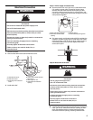
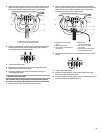
3. Connect ground wire (green or bare) of power supply cord to
external ground conductor screw. Tighten screw.
A. External ground conductor screw
B. Neutral ground wire
C. Ground wire (green or bare) of power supply cord
D. 3/4" (19 mm) UL listed strain relief
E. Center, silver-colored terminal block screw
F. Neutral wire (white or center wire)
sc
r wire)
4. Connect the other wires to outer terminal block screws. Tighten
screws.
5. Tig
hten strain relief screws.
6. Inser
t tab of terminal block cover into slot of dryer rear panel.
Secure cover with hold-down screw.
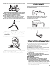
7. Y
ou have completed your electrical connection. Now go to
“Venting Requirements.”
4-wire connection: Direct wire
IMPORTANT: A 4-wire connection is required for mobile homes and
where local codes do not permit the use of 3-wire connections.
Direct wire cable must have 5 ft. (1.52 m) of extra length so dryer can
be m
oved if needed.
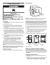
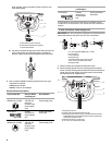
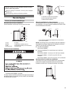
Strip 5" (127 mm) of outer covering fr
om end of cable, leaving bare
ground wire at 5" (127 mm). Cut 1
1
/2" (38 mm) from 3 remaining
wires. Strip insulation back 1" (25 mm). Shape ends of wires into a
hook shape.
1"
(25 mm)
5"
(127 mm)
When connecting to the terminal block, place the hooked end of the
wire under the screw of the terminal block (hook facing right),
squeeze hooked end together and tighten screw, as shown.
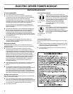
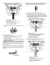
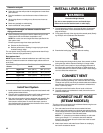
1. Remove center
, silver-colored terminal block screw.
2. Remove neut
ral ground wire from external ground conductor
screw. Connect neutral ground wire and place the hooked end
(hook facing right) of the neutral wire (white or center wire) of direct
wire cable under the center screw of the terminal block. Squeeze
hooked ends together. Tighten screw.
A
B
E
D
C
A. Neutral ground wire.
B. External ground conductor screw - Dotted line shows
position of NE
UTRAL ground wire before being moved to
center, silver-colored terminal block screw
C.Center, silver-colored terminal block screw
D. Neutral wire (white or center wire)
E. 3/4" (19 mm) UL listed strain relief
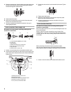
3. Connect ground wire (green or bare) of direct wire cable to
external ground conductor screw. Tighten screw.
A
C
D
F
B
E
A. External ground conductor screw
B.Neutral ground wire
C.Ground wire (green or bare) of power supply cable
D. 3/4" (19 mm) UL listed strain relief
E. Center, silver-colored terminal block screw
F. Neutral wire (white or center wire)