


18
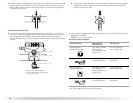
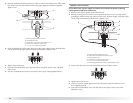
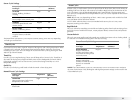
Vent system chart
NOTE: Side and bottom exhaust installations have a 90º turn inside the dryer. To determine
maximum exhaust length, add one 90º turn to the chart.
Install Vent System
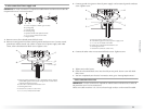
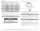
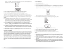
1. Install exhaust hood. Use caulking compound to seal exterior wall opening around
exhaust hood.
2. Connect vent to exhaust hood. Vent must fit inside exhaust hood. Secure vent to exhaust
hood with 4" (10.2 cm) clamp.
3. Run vent to dryer location. Use the straightest path possible. See “Determine vent path” in
“Plan Vent System.” Avoid 90º turns. Use clamps to seal all joints. Do not use duct tape,
screws or other fastening devices that extend into the interior of the vent to secure vent.
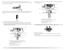
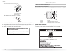
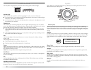
Install Leveling Legs
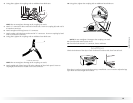
1. To protect the floor, use a large flat piece of cardboard from the dryer carton. Place
cardboard under the entire back edge of the dryer.
2. Firmly grasp the body of the dryer (not the console panel). Gently lay the dryer on the
cardboard. See illustration.
3. Examine the leveling legs. Find the diamond marking.
4. Screw the legs into the leg holes by hand. Use a wrench to finish turning the legs until the
diamond marking is no longer visible.
5. Place a carton corner post from dryer packaging under each of the 2 dryer back corners.
Stand the dryer up. Slide the dryer on the corner posts until it is close to its final location.
Leave enough room to connect the exhaust vent.
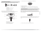
Connect Vent
1. Using a 4" (10.2 cm) clamp, connect vent to exhaust outlet in dryer. If connecting to
existing vent, make sure the vent is clean. The dryer vent must fit over the dryer exhaust
outlet and inside the exhaust hood. Check that the vent is secured to exhaust hood with a
4" (10.2 cm) clamp.
2. Move dryer into its final location. Do not crush or kink vent.
3. Once the exhaust vent connection is made, remove the corner posts and cardboard.
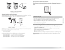
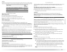
Connect Inlet Hose
The dryer must be connected to the cold water faucet using the new inlet hoses. Do not use
old hoses.
1. Turn cold water faucet off and remove washer inlet hose.
2. Remove old rubber washer from inlet hose and replace with new rubber washer provided.
If space permits, attach the brass female end of the “Y” connector to the cold water faucet.
NOTE: If “Y” connector can be attached directly to cold water faucet, go to Step 6. If “Y”
connector cannot be attached directly to the cold water faucet, the short hose must be
used. Continue with Step 3.
3. Attach short hose to cold water faucet. Screw on coupling by hand until it is seated on
faucet.
Number of 90º
turns or elbows
Type of vent Box or louvered
hoods
Angled hoods
0 Rigid metal
Flexible metal
64 ft (20 m)
36 ft (11 m)
58 ft (17.7 m)
28 ft (8.5 m)
1 Rigid metal
Flexible metal
54 ft (16.5 m)
31 ft (9.4 m)
48 ft (14.6 m)
23 ft (7 m)
2 Rigid metal
Flexible metal
44 ft (13.4 m)
27 ft (8.2 m)
38 ft (11.6 m)
19 ft (5.8 m)
3 Rigid metal
Flexible metal
35 ft (10.7 m)
25 ft (7.6 m)
29 ft (8.8 m)
17 ft (5.2 m)
4 Rigid metal
Flexible metal
27 ft (8.2 m)
23 ft (7 m)
21 ft (6.4 m)
15 ft (4.6 m)
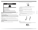
WARNING
Excessive Weight Hazard
Use two or more people to move and install dryer.
Failure to do so can result in back or other injury.