


14 Maytag Co. 113394-7
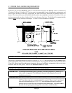
IMPORTANT: Exhaust back pressure measured by a manometer in the exhaust duct must be no less
than 0 and must not exceed 0.7 inches (1.74 mb) of water column (W.C.).
NOTE: When the exhaust ductwork passes through a wall, ceiling, or roof made of combustible
materials, the opening must be 2-inches (5.08 cm) larger than the duct (all the way around).
The duct must be centered within this opening.
NOTE: As per the National Fuel Gas Code, “Exhaust ducts for type 2 clothes dryers shall be
constructed of sheet metal or other noncombustible material. Such ducts shall be equivalent in
strength and corrosion resistance to ducts made of galvanized sheet steel not less than 26
gauge (0.0195-inches [0.50 mm]) thick.”
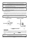
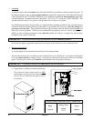
Outside Ductwork Protection
To protect the outside end of the horizontal ductwork from the weather, a 90° elbow bent downward
should be installed where the exhaust exits the building. If the ductwork travels vertically up through the
roof, it should be protected from the weather by using a 180° turn to point the opening downward. In
either case, allow at least twice the diameter of the duct between the duct opening and the nearest obstruction.
IMPORTANT: DO NOT use screens, louvers, or caps on the outside opening of the exhaust
ductwork.
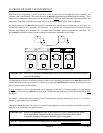
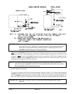
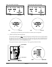
2. Single Dryer Venting
When possible, it is suggested to provide a separate exhaust duct for each dryer. The exhaust duct should
be laid out in such a way that the ductwork travels as directly as possible to the outdoors with as few turns
as possible. It is suggested that the use of 90° turns in the ducting be avoided; use 30° and/or 45° angles
instead. The shape of the exhaust ductwork is not critical as long as the minimum cross section area is
provided.
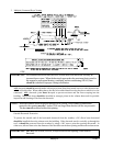
IMPORTANT: Exhaust back pressure measured by a manometer in the exhaust duct must be no less
than 0 and must not exceed 0.7 inches (1.74 mb) of water column.