


23
2.
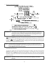
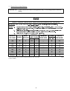
Technical Gas Data
a. Gas Specifications
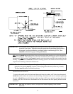
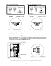
b. Gas Connections
Inlet connection------------------- 3/4 N.P.T.
Inlet supply size------------------- 3/4 Diameter Pipe (minimum)
Btu/hr input (per dryer) ---------- 175,000 (44,100 kcal/hr)
1) Natural Gas
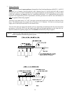
Regulation is controlled by the dryers gas valves internal regulator. Incoming supply pressure
must be consistent between a minimum of 6.0 inches (14.92 mb) and a maximum of 12.0 inches
(29.9 mb) water column (W.C.) pressure.
2) Liquid Propane (L.P.) Gas
Dryers made for use with L.P. gas have the gas valves internal pressure regulator blocked open so
that the gas pressure must be regulated upstream of the dryer. The pressure measured at each
gas valve pressure tap must be a consistent 10.5 inches (26.1 mb) water column. There is no
regulator or regulation provided in an L.P. dryer. The water column pressure must be regulated at
the source (L.P. tank) or an external regulator must be added to each dryer.
Shaded area is stated in metric equivalent
* Drill Measurement Size (D.M.S.) equivalents are as follows:
Natural Gas ................... #30 = 0.1285 (3.2639 mm).
L.P. Gas ........................ #49 = 0.0730 (1.8542 mm).
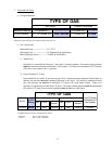
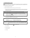
7<3( 2)*$6
/LTXLG3URSDQH
&RQYHUVLRQ.LW
3DUW1XPEHU
%WXKU
NFDOKU
5DWLQJ
1DWXUDO /LTXLG3URSDQH
4W\ '06
3DUW
1XPEHU
4W\ '06
3DUW
1XPEHU
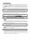
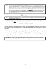
7<3(2)*$6
1$785$/ /,48,'3523$1(
0DQLIROG3UHVVXUH LQFKHV:&
PE
LQFKHV:&
PE
,Q/LQH3UHVVXUH LQFKHV:&
PE
LQFKHV:&
PE
Shaded areas are stated in metric equivalents
* Measured at outlet side of gas valve pressure tap when gas valve is on.