


Page 7
Note: In accordance with the European EMC Directive (89/336/EEC) the maximum
electricity supply system impedance to which the electric dryer should be connected is
declared to be 0.247Ω + j0.155Ω.
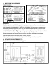
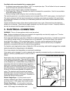
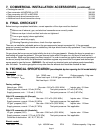
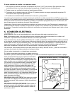
Some local wiring regulations require connection of an additional earth bond connection to
the dryer. If required, an additional earth bond wire and earth bond wire clamp are avail-
able (see Commercial Installation Accessories). The wire should be connected to the rear
panel of the dryer using the earth screw and washer as shown in the figure.
6. GAS CONNECTIONS
WARNING: The gas dryer is factory set with a burner orifice for natural gas supply (see Technical Specification). It
may be converted for use with LP butane or propane (Australia: propane only) gas using the correct conversion kit
(see Commercial Installation Accessories). Full instructions are supplied with the kit. Before installation, check that
the local distribution conditions, nature of gas and pressure, and the adjustment of the appliance are compatible.
Gas installation must be carried out in accordance with any local or national gas installation regulations by a
suitably qualified person.
Note: Single dryers are intended to be supplied by one gas supply line. Stacked pair dryers are intended to
be supplied by two gas supply lines, one to upper and one to lower dryer. The gas connection procedure is
the same for both. There is complete isolation internally between the two dryer gas systems, but before
undertaking any maintenance or servicing, both gas supplies must be disconnected.
Each dryer gas inlet connection is a 3/8” NPT thread. An adapter is supplied for conversion to ISO.7–1 thread. A
12.5mm (1/2”) gas supply line is recommended for each dryer. For multiple unit installations the size of the main
gas line must be adequate for the number of dryers (see Technical Specification for gas flow rate per dryer).
Gas connection to each dryer may be made by means of fixed pipe work or a flexible gas hose suitable for the
appliance and gas category. If flexible hose, a means of restraint should be used on the appliance to prevent
straining of the gas supply when the appliance is moved.
Remove the gas inlet connection thread protective cap. Apply joint compound or approximately 1-1/2 turns of
PTFE sealing tape over all threaded connections, and securely tighten. (Note: Jointing compound used must
be resistant to LPG.)
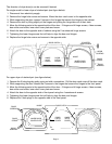
Check for leaks as directed by local or national regulations. DO NOT use a naked flame to check for gas
leaks. A pressure measurement tapping is provided on the gas valve within each dryer, accessible after
removal of the front panel. To remove this panel, remove 2 door fixing screws and opposite 2 fixing screws,
and for stacked pair the upper access panel.
Note: All gas dryers should be disconnected before any over-pressure testing of the gas supply system.
These gas dryers use an automatic ignition system to ignite the burners. There is no constant burning pilot light.
7. COMMERCIAL INSTALLATION ACCESSORIES
For all accessories and replacement parts contact your Maytag Commercial Distributor.
• Vent hood – 100mm (4”) opening . . . . . . . . . . . . . . . . . . . . . . . . . . . . . . . . . . . . . . . . . . . . . . . . . 059129
• Aluminum duct pipe – 100mm x 610mm (4” x 24”) . . . . . . . . . . . . . . . . . . . . . . . . . . . . . . . . . . . 059130
• Aluminum elbow – 100mm (4”) . . . . . . . . . . . . . . . . . . . . . . . . . . . . . . . . . . . . . . . . . . . . . . . . . . 059131
• Aluminum window plate – 381mm x 508mm (15” x 20”) with 100mm (4”) hole . . . . . . . . . . . . . . 059134
• Flexible aluminum duct – 100mm (4”) – 965mm (38”) extending to 2.44m (8’) . . . . . . . . . . . . . . 304353
• Clamp for flexible aluminum duct . . . . . . . . . . . . . . . . . . . . . . . . . . . . . . . . . . . . . . . . . . . . . . . . . 304630
• Exhaust duct kit for base and side exhausting . . . . . . . . . . . . . . . . . . . . . . . . . . . . . . . . . . . . . . . 12001453
(continued on page 8)
EARTH BOND
SCREW
(GROUND)