


Component Testing Information
!
WARNING
To avoid risk of electrical shock, personal injury or death, disconnect power to unit before servicing, unless testing
requires power.
©2005 Maytag Services 16025909 Rev. 0 21
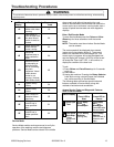
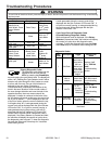
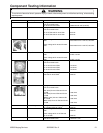
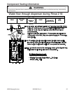
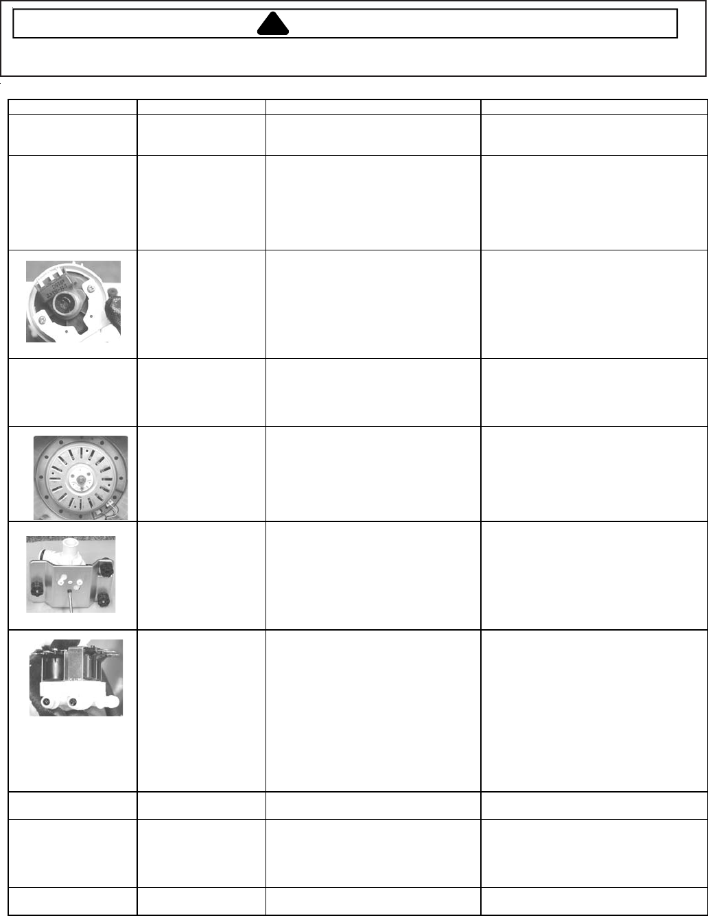
Illustration Component Test Procedure Results
Thermistor Unplug harness connector and test
from wire insertion side.
Pin #6 and Pin #3 of CN3
13000 ohms @ 70F (2.5V DC)
Door Switch Unplug harness connector and test
from wire insertion side.
Pin #7 of CN5 and Pin #3 of CN9
Pin #8 of CN5 and Pin #3 of CN9
60 ohms
60 ohms
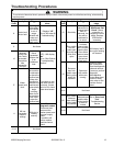
Water Sensor Check voltage at Pin #6 and Pin #7 of
CN3.
Check voltage at Pin #6 and Pin #8 of
CN3.
Reset water level = 2.5V DC, 25.8 KHz
Reset water level = 2.5V DC, 25.8 KHz
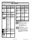
Sump Sensor
Check voltage at Pin #4 and Pin #2 of
CN8.
Check voltage at Pin #4 and Pin #3 of
CN8.
0V DC or 3.75V
0V DC or 3.75V
Motor
Unplug harness connector and test
from wire insertion side.
Pin #1 and Pin #2 of CN9
Pin #1 and Pin #3 of CN9
Pin #2 and Pin #3 of CN9
11.6 ohms
11.6 ohms
11.6 ohms
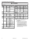
Drain Pump During drain check voltage at Pin #1 of
CN5 and Pin #6 of CN10
120V AC
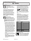
Water Valves Unplug harness connector and test
from wire insertion side.
(Hot valve) Pin #2 of CN5 and Pin #2
of CN6
(Pre valve) Pin #3 of CN5 and Pin #2
of CN6
(Bleach valve) Pin #4 of CN5 and Pin
#2 of CN6
(Main valve) Pin #1 of CN5 and Pin #2
of CN6
1100 ohms
1100 ohms
1100 ohms
1100 ohms
Heater Relay During water heat check voltage at Pin
#1 of CN5 and Pin #2 of RY9
120V AC
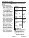
AC Power Check voltage at Pin #1 and Pin #3 of
CN5
Check voltage at Pin #1 of CN5 and
Pin #1 of CN6
120V AC
120V AC
Reactor Unplug harness connector and test
from wire insertion side.
Less than 1 ohm