


ii
4.4 Other . . . . . . . . . . . . . . . . . . . . . . . . . . . . . . . . . . . . . . . . . . . . . . . . . . . . . . . . . . . . . . . . . . . . . 31
5.0 OPERATION . . . . . . . . . . . . . . . . . . . . . . . . . . . . . . . . . . . . . . . . . . . . . . . . . . . . . . . . . . .32
5.1 Startup Checklist . . . . . . . . . . . . . . . . . . . . . . . . . . . . . . . . . . . . . . . . . . . . . . . . . . . . . . . . . . . 32
5.2 Startup . . . . . . . . . . . . . . . . . . . . . . . . . . . . . . . . . . . . . . . . . . . . . . . . . . . . . . . . . . . . . . . . . . . 32
6.0 SYSTEM MAINTENANCE . . . . . . . . . . . . . . . . . . . . . . . . . . . . . . . . . . . . . . . . . . . . . . . . . .33
6.1 General Procedures . . . . . . . . . . . . . . . . . . . . . . . . . . . . . . . . . . . . . . . . . . . . . . . . . . . . . . . . . 33
6.2 Special Procedures . . . . . . . . . . . . . . . . . . . . . . . . . . . . . . . . . . . . . . . . . . . . . . . . . . . . . . . . . . 34
6.2.1 Condenser Cleaning . . . . . . . . . . . . . . . . . . . . . . . . . . . . . . . . . . . . . . . . . . . . . . . . . . . . . . . . . . 34
6.2.2 Maintenance Inspection Checklist . . . . . . . . . . . . . . . . . . . . . . . . . . . . . . . . . . . . . . . . . . . . . . 35
FIGURES
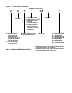
Figure i Product model nomenclature . . . . . . . . . . . . . . . . . . . . . . . . . . . . . . . . . . . . . . . . .Inside Front Cover
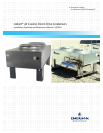
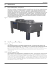
Figure 1 Liebert two-fan condenser . . . . . . . . . . . . . . . . . . . . . . . . . . . . . . . . . . . . . . . . . . . . . . . . . . . . . . . . . 1
Figure 2 Typical system configuration—indoor unit and outdoor condenser and field piping . . . . . . . . . . . 3
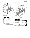
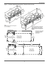
Figure 3 Condenser planning dimensional data—One-fan and two-fan units. . . . . . . . . . . . . . . . . . . . . . . . 5
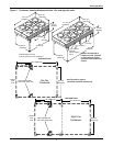
Figure 4 Condenser planning dimensional data—Three-fan and four-fan units . . . . . . . . . . . . . . . . . . . . . . 6
Figure 5 Condenser planning dimensional data—Six- and eight-fan units . . . . . . . . . . . . . . . . . . . . . . . . . . 7
Figure 6 Typical condenser footprint—dimensions . . . . . . . . . . . . . . . . . . . . . . . . . . . . . . . . . . . . . . . . . . . . . 8
Figure 7 Piping connection locations for 1-, 2-, 3- and 4-fan VFD Control and Fan Speed Condensers . . . 8
Figure 8 Piping connections for 1-, 2-, 3- and 4-fan Lee-Temp and Quiet-Line Condensers . . . . . . . . . . . . . 9
Figure 9 Piping connections for 6- and 8-fan Fan Speed Condensers. . . . . . . . . . . . . . . . . . . . . . . . . . . . . . . 9
Figure 10 Piping connections for 6- and 8-fan Lee-Temp and Quiet-Line Condensers . . . . . . . . . . . . . . . . . 10
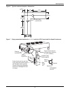
Figure 11 Equipment recommended for handling a Liebert condenser . . . . . . . . . . . . . . . . . . . . . . . . . . . . . 13
Figure 12 Removing shipping crate . . . . . . . . . . . . . . . . . . . . . . . . . . . . . . . . . . . . . . . . . . . . . . . . . . . . . . . . . 14
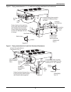
Figure 13 Attaching legs and sling to a 1-, 2-, 3- or 4-fan condenser for moving . . . . . . . . . . . . . . . . . . . . . . 15
Figure 14 Attaching legs to a 6-fan or 8-fan unit. . . . . . . . . . . . . . . . . . . . . . . . . . . . . . . . . . . . . . . . . . . . . . . 16
Figure 15 Attaching sling to a 6-fan or 8-fan unit for moving. . . . . . . . . . . . . . . . . . . . . . . . . . . . . . . . . . . . . 17
Figure 16 Wye-connected power diagram. . . . . . . . . . . . . . . . . . . . . . . . . . . . . . . . . . . . . . . . . . . . . . . . . . . . . 21
Figure 17 Delta-connected power diagram. . . . . . . . . . . . . . . . . . . . . . . . . . . . . . . . . . . . . . . . . . . . . . . . . . . . 21
Figure 18 Disconnecting EMC filter for operation with Delta-connected power . . . . . . . . . . . . . . . . . . . . . . 22
Figure 19 Electrical field connections for Fan Speed Control Condensers. . . . . . . . . . . . . . . . . . . . . . . . . . . 23
Figure 20 Electrical field connections for VFD control condensers. . . . . . . . . . . . . . . . . . . . . . . . . . . . . . . . . 24
Figure 21 Electrical field connections for Liebert Lee-Temp control condensers. . . . . . . . . . . . . . . . . . . . . . 25
Figure 22 VFD and Fan Speed Control condenser piping . . . . . . . . . . . . . . . . . . . . . . . . . . . . . . . . . . . . . . . . 27
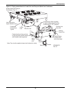
Figure 23 Lee-Temp head pressure control condenser piping. . . . . . . . . . . . . . . . . . . . . . . . . . . . . . . . . . . . . 28
Figure 24 General arrangement—Air cooled models with Lee-Temp control . . . . . . . . . . . . . . . . . . . . . . . . 29
TABLES
Table 1 Condenser shipping weights, dimensions and volume, approximate . . . . . . . . . . . . . . . . . . . . . . . 4
Table 2 Condenser physical data. . . . . . . . . . . . . . . . . . . . . . . . . . . . . . . . . . . . . . . . . . . . . . . . . . . . . . . . . . 11
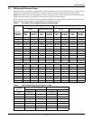
Table 3 R-22 and R-407C refrigerant required, approximate . . . . . . . . . . . . . . . . . . . . . . . . . . . . . . . . . . . 12
Table 4 Interconnecting piping refrigerant charge . . . . . . . . . . . . . . . . . . . . . . . . . . . . . . . . . . . . . . . . . . . 12
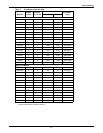
Table 5 60Hz condenser data. . . . . . . . . . . . . . . . . . . . . . . . . . . . . . . . . . . . . . . . . . . . . . . . . . . . . . . . . . . . . 19
Table 6 60Hz condenser data, Quiet-Line (Lee-Temp controlled/fan-cycling) . . . . . . . . . . . . . . . . . . . . . . 19
Table 7 50Hz condenser full load amp values. . . . . . . . . . . . . . . . . . . . . . . . . . . . . . . . . . . . . . . . . . . . . . . . 19
Table 8 Lee-Temp receiver electrical data, 50Hz and 60Hz . . . . . . . . . . . . . . . . . . . . . . . . . . . . . . . . . . . . 20
Table 9 Troubleshooting. . . . . . . . . . . . . . . . . . . . . . . . . . . . . . . . . . . . . . . . . . . . . . . . . . . . . . . . . . . . . . . . . 36