


Introduction
3
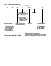
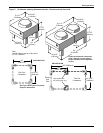
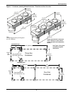
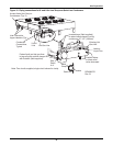
Figure 2 Typical system configuration—indoor unit and outdoor condenser and field piping
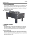
Lee-Temp Receiver
Fan Speed and VFD
Lee-Temp
Service
Valve
External
Equalizer
Liquid
Sensing
Bulb
Inverted trap on discharge & liquid
lines to extend above base of coil
by a minimum of 7-1/2” (190mm).
Field-installed relief valve (s) required
for 50 Hz EU CE units rated maximum
480 PSIG (33 Bar).
* Isolation
valve
* Traps every
25ft (7.6m)
of rise
Fusible
Plug
Suction
Hot Gas Discharge
Liquid Return
Filter DryerSight Glass
Solenoid
Valve
Expansion
Valve
DPN000798
Rev. 2
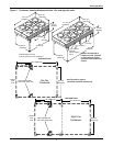
Condenser Coil
(Fan Speed
and VFD)
Condenser Coil
(Lee-Temp)
Evaporator Coil
Compressor
Service
Valve
Check
Valve
* Isolation
valve
28-42kW Digital Solenoid Valve
53-70kW Digital
Solenoid Valve
Factory Refrigerant Piping
Field Refrigerant Piping
Service/Schrader (Access) Connection No Valve Core
Note: Schematic representation shown . Do not use for specific connection locations.
Two refrigeration circuits provided . Single refrigeration circuit shown for clarity .
Service/Schrader (Access) Connection With Valve Core
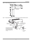
Liquid Return
Hot Gas
Discharge
Head Pressure
Control Valve
Check
Valve
Relief
Valve
Service
Valve
Components are not supplied by
Liebert, but are recommended
for proper circuit operation and
maintenance.
*
Pitch horizontal hot gas piping
1/2" per 10 ft. (42mm per 10m)
in direction of refrigerant/oil flow.