


11
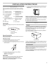
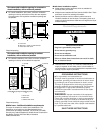
Determine vent path
■ Select the route that will provide the straightest and most
direct path outdoors.
■ Plan the installation to use the fewest number of elbows and
turns.
■ When using elbows or making turns, allow as much room as
possible.
■ Bend vent gradually to avoid kinking.
■ Use the fewest 90° turns possible.
Determine vent length and elbows needed for best
drying performance
■ Use one of the following Vent system charts to determine
type of vent material and hood combinations acceptable to
use.
NOTE: Do not use vent runs longer than those specified in
the Vent system charts. Exhaust systems longer than those
specified will:
■ Shorten the life of the dryer.
■ Reduce performance, resulting in longer drying times and
increased energy usage.
The Vent system charts provide venting requirements that will
help to achieve the best drying performance.
Vent system chart 1 - rigid metal vent only
Vent system chart 2 - rigid metal vent used with a
maximum of 8 ft (2.4 m) flexible metal vent
Install Vent System
1. Position the dryer so that the rear of the dryer is within 4 ft
(1.2 m) of its final location.
2. Install exhaust hood. Use caulking compound to seal exterior
wall opening around exhaust hood.
3. Connect vent to exhaust hood. Vent must fit inside exhaust
hood. Secure vent to exhaust hood with 4" (10.2 cm) clamp.
4. Run vent to dryer location. Use the straightest path possible.
See “Determine vent path” in “Plan Vent System.” Avoid 90º
turns. Use clamps to seal all joints. Do not use duct tape,
screws or other fastening devices that extend into the interior
of the vent to secure vent.
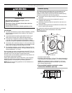
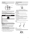
Make Gas Connection
1. Remove the blue cap from the gas pipe. Move the dryer close
to its final location.
2. Using a wrench to tighten, connect the gas supply to the
dryer. Use pipe-joint compound on all non-flared male
threads. If flexible metal tubing is used, be sure there are no
kinks.
NOTE: For LP gas connections, you must use pipe-joint
compound resistant to the action of LP gas. Do not use
TEFLON
®†
tape.
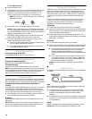
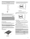
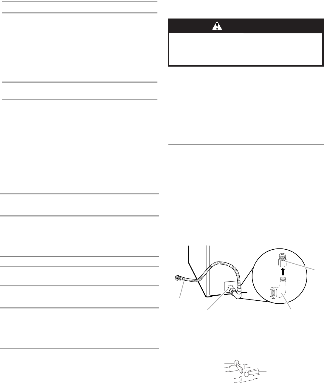
A combination of pipe fittings must be used to connect the
dryer to the existing gas line. Shown following is a
recommended connection. Your connection may be different,
according to the supply line type, size and location.
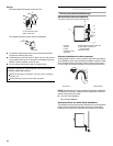
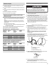
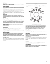
3. Open the shutoff valve in the supply line. The valve is open
when the handle is parallel to the gas pipe.
4. Test all connections by brushing on an approved
noncorrosive leak-detection solution. Bubbles will show a
leak. Correct any leak found.
Number of
90º turns
or elbows
Type of
vent
Box or
louvered
hoods
Angled
hoods
0 Rigid metal 174 ft (53.0 m) 168 ft (51.2 m)
1 Rigid metal 164 ft (50.0 m) 158 ft (48.0 m)
2 Rigid metal 154 ft (46.9 m) 148 ft (45.1 m)
3 Rigid metal 145 ft (44.2 m) 139 ft (42.4 m)
4 Rigid metal 137 ft (41.8 m) 131 ft (39.9 m)
Number of
90º turns
or elbows
Type of
vent
Box or
louvered
hoods
Angled
hoods
0 Rigid metal 144 ft (43.9 m) 138 ft (42.1 m)
1 Rigid metal 134 ft (40.8 m) 128 ft (39.0 m)
2 Rigid metal 125 ft (38.1 m) 119 ft (36.3 m)
3 Rigid metal 117 ft (35.7 m) 111 ft (33.8 m)
A.
³⁄₈
" flexible gas connector
B.
³⁄₈
" dryer pipe
C.
³⁄₈
" to
³⁄₈
" street el
D.
³⁄₈
" pipe-to-flare adapter fitting
A.Closed valve
B. Open valve
WARNING
Excessive Weight Hazard
Use two or more people to move and install dryer.
Failure to do so can result in back or other injury.
†®TEFLON is a registered trademark of E.I. Du Pont De Nemours and Company.
A
B
C
D
A
B