


3
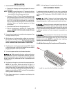
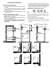
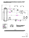
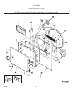
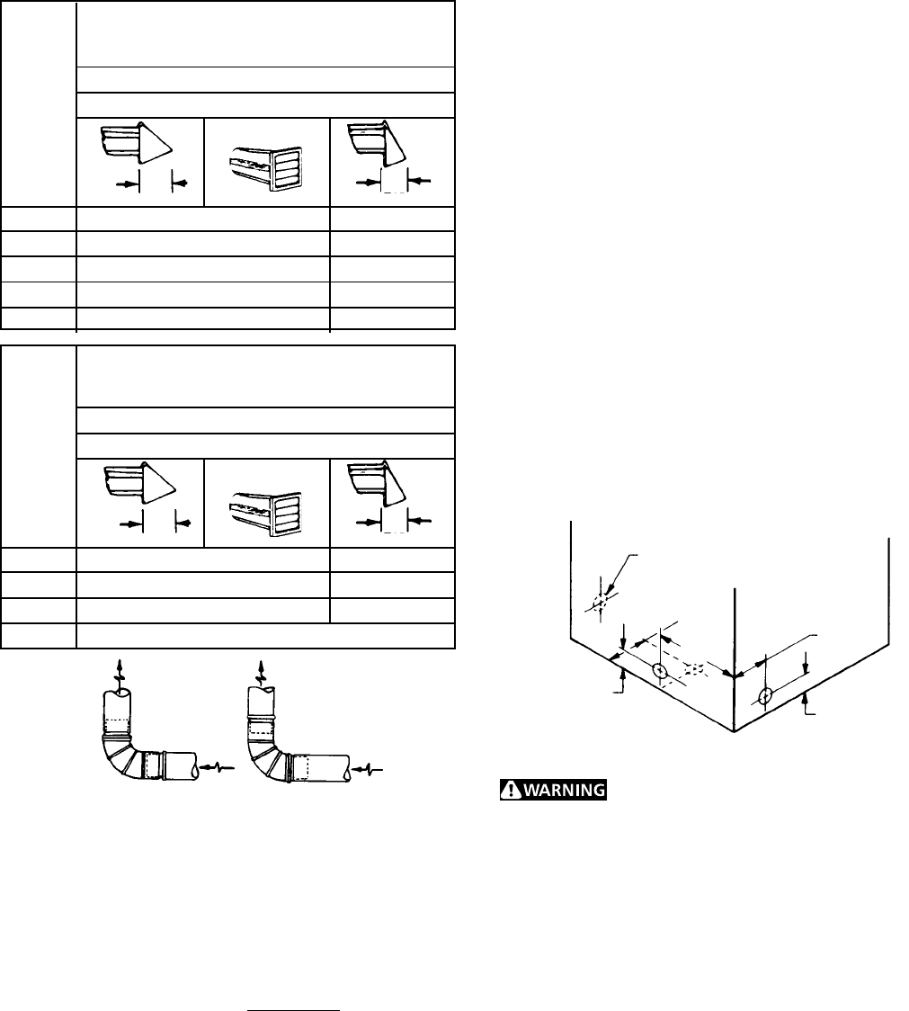
INSTALL MALE FITTINGS IN CORRECT DIRECTION
CORRECT
INCORRECT
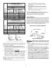
0 60 ft. (18.28 m) 48 ft.(14.63 m)
1 52 ft. (15.84 m) 40 ft.(12.19 m)
2 44 ft. (13.41 m) 32 ft. (9.75 m)
3 32 ft. (9.75 m) 24 ft. (7.31 m)
4 28 ft. (8.53 m) 16 ft. (4.87 m)
0 30 ft. (9.14 m) 18 ft. (5.49 m)
1 22 ft. (6.71 m) 14 ft. (4.27 m)
2 14 ft. (4.27 m) 10 ft. (3.05 m)
3 NOT RECOMMENDED
VENT HOOD TYPE
(Preferred)
MAXIMUM LENGTH
of 4” (10.2 cm) Dia. Flexible Metal Duct
Number
of
90°
Turns
4”
(10.2 cm)
Louvered
VENT HOOD TYPE
(Preferred)
Number
of
90°
Turns
MAXIMUM LENGTH
of 4” (10.2 cm) Dia. Rigid Metal Duct
4”
(10.2 cm)
Louvered
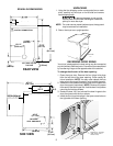
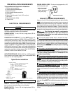
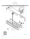
SAME AS OTHER SIDE
(9.5 cm)
4 3/8"
(11 cm)
5 7/8"
(15 cm)
13 1/2"
(34 cm)
3 3/4"
(9.5 cm)
3 3/4"
(9.5 cm)
(6.35 cm)
2½"
(6.35 cm)
2½"
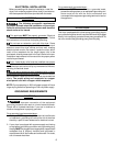
In installations where the exhaust system is not described in the
charts, the following method must be used to determine if the
exhaust system is acceptable:
1. Connect an inclined or digital manometer between the
dryer and the point the exhaust connects to the dryer.
2. Set the dryer timer and temperature to air fluff (cool
down) and start the dryer.
3. Read the measurement on the manometer.
4. The system back pressure MUST NOT be higher than
0.75 inches of water column. If the system back
pressure is less than 0.75 inches of water column, the
system is acceptable. If the manometer reading is
higher than 0.75 inches of water column, the system is
too restrictive and the installation is unacceptable.
Although vertical orientation of the exhaust system is
acceptable, certain extenuating circumstances could affect the
performance of the dryer:
• Only the rigid metal duct work should be used.
• Venting vertical through a roof may expose the ex
haust system to down drafts causing an increase in
vent restriction.
• Running the exhaust system through an uninsulat-
ed area may cause condensation and faster accumu
lation of lint.
• Compression or crimping of the exhaust system will
cause an increase in vent restriction.
The exhaust system should be inspected and cleaned a
minimum of every 6 months with normal usage. The more the
dryer is used, the more often you should check the
exhaust system and vent hood for proper operation.
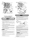
EXHAUST DIRECTION
All dryers shipped from the factory are set up for rear exhausting.
However, on electric dryers, exhausting can be to the right or left
side of the cabinet or the bottom of the dryer. On gas dryers,
exhausting can be to the right side of the cabinet or the bottom of
the dryer. Directional exhausting can be accomplished by installing
Exhaust Kit, P/N 131456800, available through your parts
distributor. Follow the instructions supplied with the kit.
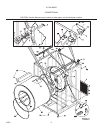
EXHAUST DUCT LOCATING DIMENSIONS
GAS SUPPLY REQUIREMENTS
Replace copper connecting pipe that is not
plastic-coated. Stainless steel or plastic-coated brass MUST
be used.
1. Installation MUST conform with local codes, or in the absence
of local codes, with the National Fuel Gas Code, ANSI Z223.1
(latest edition).
2. The gas supply line should be of 1/2 inch (1.27 cm) pipe.
3. If codes allow, flexible metal tubing may be used to connect
your dryer to the gas supply line. The tubing MUST be
constructed of stainless steel or plastic-coated brass.
4. The gas supply line MUST have an individual shutoff valve.
5. A 1/8 inch (0.32 cm) N.P.T. plugged tapping, accessible for
test gauge connection, MUST be installed immediately
upstream of the gas supply connection to the dryer.
6. The dryer MUST be disconnected from the gas supply piping
system during any pressure testing of the gas supply piping
system at test pressures in excess of 1/2 psig (3.45 kPa).
7. The dryer MUST be isolated from the gas supply piping system
during any pressure testing of the gas supply piping system
at test pressures equal to or less than 1/2 psig (3.45 kPa).