


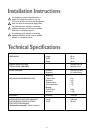
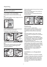
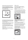
Water inlet
Connect the hose to a tap with a 3/4” thread.
Always use the hose supplied with the appliance to
connect to the water supply.
Do not use previously used hoses for water
connection.
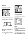
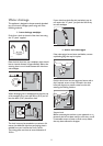
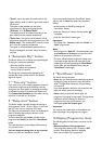
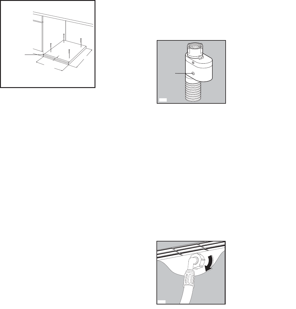
The inlet hose is provided with a water stop device,
which protects against damage caused by water leaks in
the hose which could develop due to natural ageing of
the hose. This fault is shown by a red sector in the
window “A”. Should this occur, turn the water tap off
and refer to your Service Centre to replace the hose.
Installation should comply with local water authority
and building regulations’ requirements.
The appliance must be connected to a cold
water supply.
A minimum water pressure of 0.05 MPa (0.5 bar) is
required for safe operation of the appliance.
If you cannot make the cold water connection direct
from the rising mains, you may be able to operate the
appliance from your cold water storage system.
There should be a minimum distance of 5.02m
(16.5 ft) between the appliance’s inlet and the bottom
of the water storage tank.
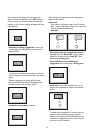
Set the hose correctly by loosening the ring nut. After
positioning the inlet hose, be sure to tighten the ring
nut again to prevent leaks.
P0021
A
P0352
10
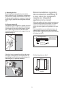
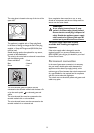
Position the base into the recess with its front edge as
far forward as the adjoining plinth line will allow.
The reason for placing the base in this position
is to allow a small strip of beading to be fitted in
front of the appliance feet.
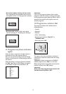
Fix the base firmly to the floor using four appropriate
countersunk screws (see Fig. H).
With the appliance installed adjust all four feet ensuring
the machine is stable, and a clearance of approximately
5 mm is left between the top of the machine and the
underside of the worktop.
A final check for stability should be carried out with the
machine on spin with a load, this will identify the need
for any further fine adjustment to the feet.
A strip of beading approximately 605 mm W, x 5 mm
H, x 25 mm D must be screwed down into the base
directly in front of the machine’s feet, this will provide
additional security.
If required an additional door magnet, part number
1242394-00/3 and disc, part number 1242393-00/5 are
available from spare parts.
600-605
5 X 25 X 605
Hardwood strip
5 mm x 25 mm
H
490