


Commissioning
The units are factory pre-set and commissioned and should not need any field adjustment. However, if after a
period of time the unit is found to be operating poorly or incorrectly, this may be due to a range of faults or
problems which may be analysed by reference to the Fault Finding section of this manual.
Start-up Procedure
Important
Do not allow the compressed air to flow through the unit until the following checks have been made
AND THE UNIT SWITCHED ON.
1. Switch the on-off switch / isolator to the "ON" (I) position. The following observations will indicate correct
operation:
The fan will start
An airflow will be felt from the condenser discharge grille
After 2 minutes, the compressor will start and a low-level noise will be heard similar to that of a
domestic refrigerator.
2. After a further 5 minutes, slowly allow the compressed air supply into the dryer.
3. Press the VALVE button to check the operation of the condensate discharge valve.
Note:
Some safety cut outs are auto reset, and unless isolated from the mains the unit can be re-started without
warning.
Pressure switches should be adjusted with the power off.
Any work done to the Compressed Air Dryer involving entry into the control panel, fitting gauges, adjusting
controls, charging the system, evacuating the system or opening the system in any way, must be carried out
by a FULLY QUALIFIED REFRIGERATION ENGINEER. A City and Guilds 2078 or equivalent certificate is
strongly advised and will soon be mandatory.
Description of Operation
The saturated compressed air enters the evaporator and is pre-cooled by the outgoing cooler air. The internal
refrigerant circuit is then used to further cool the air to its required dewpoint. Once dewpoint is achieved, the
moisture condenses, and the water droplets are ejected via the condensate drain system. The cold, dry air is
then warmed by the incoming warm air and discharged, dry, to the downstream pipework.
The refrigerant circuit is of conventional design operating on ozone benign Refrigerant R134a of R407c and
incorporates an hermetic compressor, combined air/air and evaporator type heat exchanger, an air cooled
condenser, an expansion device (capillary tube or thermostatic expansion valve), a filter/dryer, a hot gas by-
pass valve. The refrigeration circuit is controlled by means of a simple but effective panel mounted controller
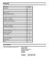
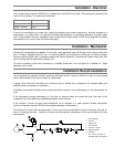
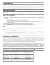
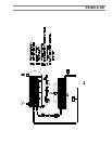
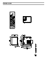
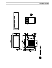
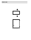
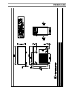
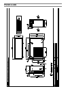
Schematic Flow and General Arrangement Drawings
Model NumbersSchematic Flow
Diagram Number
Outline Arrangement
Drawing Number
C9-1, C14-1, C19-1PS1061-C-021PS1061-C-001
C31-2, C39-2, C58-2PS1061-C-021PS1061-C-002
C92-3, C120-3PS1061-C-021PS1061-C-003
C147-3PS1061-C-021PS1061-C-004
C175-4, C238-4PS1061-C-021PS1061-C-005