


Portable Dryer Troubleshooting
85
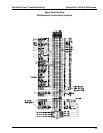
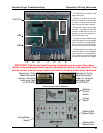
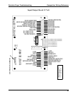
P3 P2 P1 L1 L2 A-A+
MIN
MAX
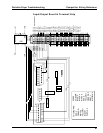
* The SCR board is located in the
upper control box.
* Terminals L1 and L2 are the input
terminals. When the unload system
is turned on there should be 220
Volts AC accross these terminals.
* Terminals A+ and A- are the ouput
terminals. The voltage across these
terminals is DC and will vary de-
pending on where the speed con-
trol potentiometer is set.
* The item circled at the bottom right
of the SCR board in the photograph
is the minimum set potentiometer.
This will be used in the SCR board
set up to set minimum DC voltage.
* The item circled at the bottom left
of the SCR board in the photograph
is the maximum set potentiometer.
This will be used in the SCR board
set up to set maximum DC voltage.
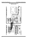
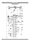
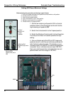
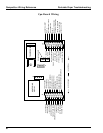
Unload
Switch
Drying Mode
Switch
Metering Roll
Speed (High)
Metering Roll
Speed (Low)
Control panel switch locations.
Moisture
Control
Switch
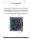
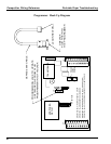
IMPORTANT: After the new board has been installed be sure to remove the resistor
(shown in the photograph above) from the old board and install it in the new board. Just
pull the resistor from the two pin socket and install in the same socket on the new board.
Resistor for 1/3 Hp
Meter Roll motors
used on 12 ft dryers
and shorter. (part
no. D03-0039)
Resistor for 3/4 Hp
Meter Roll motors
used on 14 ft dryers
and longer. (part
no. D33-0001)
RESISTOR
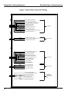
Competitor Wiring Reference