


=BC0;;0C8>==BCAD2C8>=B
!)'!'&*'"#)(
$'!)''.'(
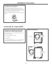
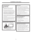
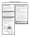
This dryer must be connected to an individual
branch circuit, protected by the required time-
delay fuses or circuit breakers. A three- or four-
wire, single-phase, 120/240V, 60Hz, 30-amp
circuit is required.
If the electric supply does not meet the above
specifications, then call a licensed electrician.
'$*###()'*)$#(
This dryer must be connected to a grounded metal,
permanent wiring system, or an equipment-
grounding conductor must be run with the circuit
conductors and connected to the equipment
grounding terminal on the appliance.
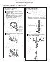
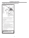
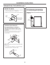
$##)#'.'*(#,'
$##)$#"*()*($'
"$!$"#()!!)$#
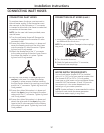
#$) Since January 1, 1996, the National Electrical
Code requires that new constructions utilize a
4-wire connection to an electric dryer. A 4-wire cord
must also be used where local codes do not permit
grounding through the neutral.
3-wire connection is NOT for use on new
construction.
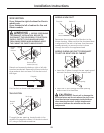
Remove ground
strap and
discard. Keep
green ground
screw
Hot Wire
Relocate green ground
screw here
Green Wire
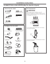
Strain Relief
Bracket
3/4″ UL Recognized
Strain Relief
Hot Wire
Neutral
(white)
Screws (3)
Cover
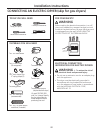
4 #10 AWG minimum copper
conductors or 120/240V 30A power
supply cord kit marked for use with
dryers and provided with closed loop
or spade terminals with upturned
ends (not supplied)
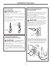
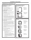
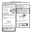
$##)#'.'*(#,'
$##)$#"*()*($'
"$!$"#()!!)$#2>=C
,'##M#+'!+)
$+'$$))'"#!!$
Turn off the circuit breaker(s) (30 amp) or remove
the dryer’s circuit fuse at the electrical box.
Be sure the dryer cord is unplugged from
the wall receptacle.
Remove the power cord cover located at
the lower back.
Remove and discard ground strap. Keep
the green ground screw for Step 7.
Install 3/4 in. UL-recognized strain relief to power
cord entry hole. Bring power cord through strain
relief.
Connect power cord as follows:
Connect the 2 hot lines to the outer screws
of the terminal block (marked L1 and L2).
Connect the neutral (white) line to the center
of the terminal block (marked N).
Attach ground wire of power cord with the green
ground screw (hole above strain relief bracket).
Tighten all terminal block screws (3) completely.
Properly secure power cord to strain relief.
Reinstall the cover.