


73
4.
RTD (Resistive Temperature Device) WIRING TO THE EXHAUST 4 to 20 MILLIAMPERE
(4 to 20 mA) TRANSMITTER
Check ALL wiring and MLS-460 connection from the exhaust RTD (Resistive Temperature Device) probe
to the exhaust 4 to 20 milliampere (4 to 20 mA) transmitter. Refer to the MLS-460 EXHAUST Temperature
Assembly and Wiring Diagram, MLS-460 Main Panel Wiring Diagram.
5. CIRCUIT WIRING TO THE ANALOG INPUT MODULE
Check ALL wiring and connections from the 4 to 20 milliampere (4 to 20 mA) transmitter to the PLC
(Programmable Logic Controller) Analog Input Module. Refer to the MLS-460 Main Panel Wiring Diagram.
F. MOTORS
INTRODUCTION
The four (4) motors installed on the MLS-460 are connected directly to associated thermal magnetic starters in
the main electrical enclosure. The troubleshooting information included in this section will cover the actuation,
power control and safety devices to these motors.
The MLS-460 motors include:
MAIN BLOWER FAN MOTOR
BURNER FAN MOTOR
LEFT TUMBLER (BASKET) MOTOR
RIGHT TUMBLER (BASKET) MOTOR
Refer to the following diagrams for functional and wiring information:
MLS-460 MAIN PANEL WIRING DIAGRAM
MLS-460 SYSTEM BLOCK DIAGRAM
Motor Actuating Device Information
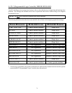
ALL MLS-460 motor contactors have 110 volts 50/60 Hz actuation coils. Three (3) motor contactors
are actuated by outputs from the PLC (Programmable Logic Controller), and one contactor is actuated
by the Burner Controller Module (BCM).
Motor Protection Device Descriptions
The motor protection devices in the MLS-460 incorporate a manual disconnect switch, thermal overload
relay, and instantaneous trip mechanism in one compact device. A two (2) position, normally open,
auxiliary contact block has been attached to ALL motor protection devices to provide the MOTOR
FAULT display message, and shut down ALL motors in the event a motor should trip.
1. MOTOR ACTUATION PROBLEMS
a. PROBABLE CAUSES;
1) Motor Protection Device OFF or TRIPPED.