


18
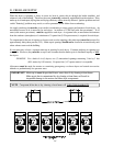
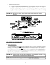
3. Multiple Dryer (common) Venting
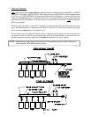
If it is not feasible to provide separate exhaust ducts for each dryer, ducts from individual dryers may be
channeled into a "common main duct." The individual ducts should enter the bottom or side of the main duct
at an angle not more than 45º in the direction of airflow and should be spaced at least 46-inches (116.84
cm) apart. The main duct should be tapered, with the diameter increasing before each individual duct (16-
inch [40.64 cm] minimum) is added.
IMPORTANT: The ML-96 is not provided with a back draft damper unless the damper option was
purchased. When exhausted into a multiple (common) exhaust line, a back draft
damper must be installed at each dryer duct.
IMPORTANT: No more than three (3) dryers should be connected to main common duct.
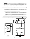
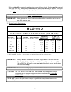
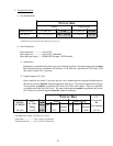
The main duct may be any shape so long as the minimum cross section is provided. The illustration on page
19 shows the minimum cross section area for multiple dryer round or square venting. These figures must
be increased 10 square inches (64.5 square centimeters) when rectangular main ducting is used, and the
ratio of duct width to depth should not be greater than 3-1/2 to 1. These figures must be increased in
proportion if the main duct run from the last dryer to where it exhausts to the outdoors is unusually long (over
20 feet [6.1 meters]) or has numerous (more than two [2] elbows in it). In calculating ductwork size, the
cross section area of a square or rectangular duct must be increased twenty percent (20%) for each
additional 20 feet (6.1 meters). The diameter of a round exhaust must be increased ten percent (10%) for
each additional 20 feet (6.1 meters). Each 90º elbow is equivalent to an additional 36 feet (10.97 meters)
and each 45º elbow is equivalent to an additional 15 feet (4.57 meters).
IMPORTANT: For extended ductwork runs, the cross section area of the ductwork can only be
increased to an extent. Maximum proportional ductwork runs cannot exceed 15 feet
(4.57 meters) with two (2) elbows. When the ductwork approaches the maximum
limits as noted in this manual, a professional heating, venting, and air conditioning
(HVAC) firm should be consulted for proper venting information.
IMPORTANT: Exhaust back pressure measured by a manometer at each dryer exhaust duct area
must not exceed 0.3 inches (0.75 mb) of water column (W.C.).
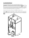
The ductwork should be smooth inside with no projections from sheet metal screws or other obstructions,
which will collect lint. When adding ducts, the duct to be added should overlap the duct to which it is to be
connected. ALL ductwork joints must be taped to prevent moisture and lint from escaping into the building.
Inspection doors should be installed at strategic points in the exhaust ductwork for periodic inspection and
cleaning of lint from the ductwork.
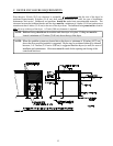
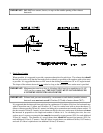
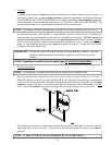
NOTE: When the exhaust ductwork passes through a wall, ceiling, or roof made of combustible
materials, the opening must be 2-inches (5.08 cm) larger than the duct (ALL the way around).
The duct must be centered within this opening.