


113362-11 www.amdry.com 11
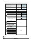
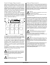
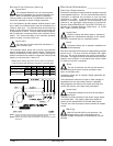
NUMBER OF DRYERS 4 3 2 1
MINIMUM CROSS-
SECTIONAL AREA
SQ IN 650 540 324 210
SQ CM 4194 3484 2090 1354
MINIMUM ROUND
DUCT DIAMETER
IN 28 26 20 16
CM 71.12 66.04 50.8 40.64
!
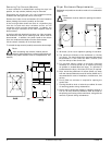
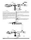
NOTE 1 Opening must be 2-inches (5.08 cm) larger than the duct (all the way
around). The duct must be centered within this opening.
NOTE 2 Distance should be 2 times the diameter of the duct to the nearest
obstruction.
!
Multiple Dryer (Common) Venting
Important
For extended ductwork runs, the cross-sectional
area of the ductwork can only be increased to an
extent. When the ductwork approaches the maximum
limits as noted in this manual, a professional HVAC firm
should be consulted for proper venting information.
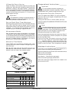
If it is not feasible to provide separate exhaust ducts for each
dryer, ducts from individual dryers may be channeled into a
“common main duct.” The individual ducts should enter the
bottom or side of the main duct at an angle not more than 45°
in the direction of airflow. The main duct should be tapered,
with the diameter increasing before each individual duct is
added. The minimum diameter of the individual ductwork
must be at least 16-inches (40.64 cm).
Important
No more than 4 dryers should be connected to 1
main common duct.
The illustration below shows the minimum cross-sectional
area for multiple dryer round or square venting. These figures
must be increased if the main duct run from the last dryer to
where it exhausts to the outdoors is longer than 20 feet (6.096
meters) or has more than 1 elbow in it.
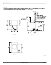
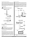
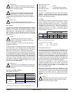
Multiple Dryer Venting (Gas) with 16-Inch (40.64 cm) Diameter
2,700 cfm (76.46 cmm) Exhaust Connections at Common Duct
Electrical Information _________________
Electrical Requirements
All electrical connections must be made by a properly licensed
and competent electrician. This is to ensure that the electrical
installation is adequate and conforms to local and state
regulations or codes. In the absence of such codes, all
electrical connections, materials, and workmanship must
conform to the applicable requirements of the National
Electrical Code ANSI/NFPA NO. 70-LATEST EDITION or in
Canada, the Canadian Electrical Codes Parts 1 & 2 CSA
C22.1-1990 or LATEST EDITION.
Important
Failure to comply with these codes or ordinances,
and/or the requirements stipulated in this manual
can result in personal injury or component failure.
Note
Component failure due to improper installation will
void the warranty.
Each dryer should be connected to an independently protected
branch circuit. The dryer must be connected with copper
wire only. Do not use aluminum wire, which could cause a
fire hazard. The copper conductor wire/cable must be of proper
ampacity and insulation in accordance with electric codes
for making all service connections.
Note
The use of aluminum wire will void the warranty.
An individual ground circuit must be provided to each
dryer, do not daisy chain.
Component failure due to improper voltage application will
void the warranty.
The manufacturer reserves the right to make changes in
specifications at any time without notice or obligation.
Wiring diagrams are affixed to the inside at the top front
control door and the rear upper back guard/panel.
Impor tant
A separate protected circuit must be provided to
each dryer.
The dryer must be connected to the electric supply shown
on the data label. The supply voltage must match the
electric service specifications of the data label exactly.
The wire size must be properly sized to handle the related
current.
Warning
208 VAC and 240 VAC are not the same. Any
damage done to dryer components due to
improper voltage connections will automatically void the
warranty.
!
!
!
!
!
A = 16-inches (40.64 cm)
B = 20 feet (6.096 meters)