


12
American Dryer Corp.
113345-9
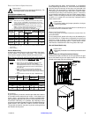
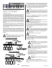
TYPE OF GAS
Btu/hr
Rating
kcal/hr
Rating
Natural Liquid Propane
Qty. D.M.S.* Part No. Qty. D.M.S.* Part No.
160,000 40,320 3 #29 140820 3 #48 140804
Liquid Propane Conversion Kit Part Number 881598
Shaded area is stated in metric equivalent
* Drill Measurement Size (D.M.S.) equivalents are as follows:
Natural Gas ............. #29 = 0.1360” (3.4544 mm).
Liquid Propane Gas .. #48 = 0.0760” (1.9304 mm).
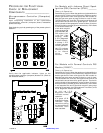
Piping/Connections
All components/materials must conform to National Fuel Gas
Code Specifications ANSI Z223.1-LATEST EDITION, or in
Canada, CAN/CGA-B149.1-M91 (Natural Gas) or CAN/CGA-
B149.2-M91 (Liquid Propane [L.P.] Gas) or LATEST EDITION
(for General Installation and Gas Plumbing), as well as local
codes and ordinances and must be done by a qualified
professional. It is important that gas pressure regulators
meet applicable pressure requirements, and that gas meters
be rated for the total amount of all the appliance Btus being
supplied.
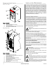
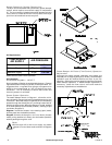
The dryer is provided with a 3/4” N.P.T. inlet pipe connection
located at the rear upper left side of the dryer. The minimum
pipe size (supply line) to the dryer is 3/4” diameter. For ease
in servicing, the gas supply line of each dryer must have its
own shutoff valve.
The size of the main gas supply line (header) will vary
depending on the distance this line travels from the gas meter
or, in the case of (L.P.) gas, the supply tank, other gas-operated
appliances on the same line, etc. Specific information
regarding supply line size should be determined by the gas
supplier.
Note
Undersized gas supply piping can create a low or
inconsistent pressure, which will result in erratic
operation of the burner ignition system.
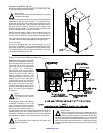
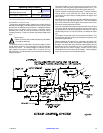
Consistent gas pressure is essential at all gas connections.
It is recommended that a 3/4-inch (19.05 mm) pipe gas loop
be installed in the supply line servicing a bank of dryers. An
in-line pressure regulator must be installed in the gas supply
line (header) if the (natural) gas pressure exceeds 12.0
inches (29.9 mb) of water column pressure (W.C.).
Note
A water column (W.C.) test pressure of 3.5 inches
(8.7 mb) for natural gas and 10.5 inches (26.1 mb)
for liquid propane (L.P.) dryers is required at the
gas valve pressure tap of each dryer for proper and safe
operation.
A 1/8” N.P.T. plugged tap, accessible for a test gauge
connection, must be installed in the main gas supply line
immediately upstream of each dryer.
Important
Pipe joint compounds that resist the action of natural
gas and L.P. gas must be used.
Test all connections for leaks by brushing on a soapy water
solution (liquid detergent works well).
The dryer and its individual shutoff valve must be
disconnected from the gas supply piping system during any
pressure testing of that system at test pressures in excess of
1/2 psig (3.5 kPa).
Note
The dryer must be isolated from the gas supply piping
system by closing its individual manual shutoff valve
during any pressure test of the gas supply system
at test pressures equal to or less than 1/2 psig (3.5 kPa).
Warning
Never test for leaks with a flame!!!
Steam Information _____________________
It is your responsibility to have all plumbing connections made
by a qualified professional to ensure that the steam plumbing
installation is adequate and conforms with local and state
regulations or codes.
!
!
!
!
!
Important
Failure to comply with the requirements stipulated
in this manual can result in component failure,
which will void the warranty.
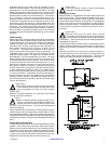
Note
The dryer is manufactured with a pneumatic
(piston) damper system, which requires an
external supply of air of 0.75 cfh at 80 psi ± 10
psi (0.02 cmh at 5.52 bar ± 0.68 bar]).
Steam Coil pH Level
The normal pH level for copper type steam coils must be
maintained between a value of 8.5 to 9.5. For steel type
steam coils the pH level must be maintained between a
value of 9.5 to 10.5. These limits are set to limit the acid
attack of the steam coils.
Important
Coil failure due to improper pH level will void the
warranty.
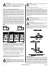
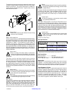
Steam Requirements – High Pressure
Inlet: 1” supply line connection, qty. one (1) at top manifold.
Return: 1” return line connection, qty. one (1) at bottom
manifold.
!
!
!