


113345-9
www.amdry.com
11
!
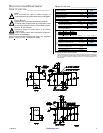
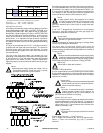
Type of Gas
Manifold Pressure* In-Line Pressure
Natural
3.5 inches W.C. 6.0-12.0 inches W.C.
8.7 mb 14.92 - 29.9 mb
Liquid
Propane
10.5 inches W.C. 11.0 inches W.C.
26.1 mb 27.4 mb
!
!
!
!
!
!
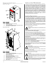
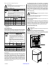
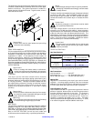
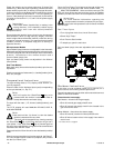
The electrical input connections are made at the electric oven
contactor located inside the assembly at the rear center upper
section of the dryer. The ground connection is made to a
copper lug also provided in this area. To gain access, remove
oven rear service cover.
Important
A strain relief must be used where the input wiring
enters the oven assembly.
Gas Information ______________________
It is your responsibility to have all plumbing connections made
by a qualified professional to ensure that the gas plumbing
installation is adequate and conforms with local and state
regulations or codes. In the absence of such codes, all
plumbing connections, materials, and workmanship must
conform to the applicable requirements of the National Fuel
Gas Code ANSI Z223.1-LATEST EDITION, or in Canada, the
Canadian Installation Codes CAN/CGA-B149.1-M91 (Natural
Gas) or CAN/CGA-B149.2-M91 (Liquid Propane [L.P.] Gas) or
LATEST EDITION.
Important
Failure to comply with these codes or ordinances,
and/or the requirements stipulated in this manual,
can result in personal injury and improper operation
of the dryer.
The dryer and its individual shutoff valves must be
disconnected from the gas supply piping system during any
pressure testing of that system at test pressures in excess
of 1/2 psig (3.5 kPa). The dryer must be isolated from the
gas supply piping system by closing its individual manual
shutoff valve during any pressure test of the gas supply
system at test pressures equal to or less than 1/2 psig
(3.5 kPa).
Important
Failure to isolate or disconnect the dryer from supply
as noted can cause irreparable damage to the gas
valve, which will void the warranty.
Warning
Fire or explosion could result due to failure of isolating
or disconnecting the gas supply as noted.
Gas Supply
The gas dryer installation must meet the American National
Standard...National Fuel Gas Code ANSI Z223.1-LATEST
EDITION, or in Canada, the Canadian Installation Codes CAN/
CGA-B149.1 M91 (Natural Gas) or CAN/CGA-B149.2-M91 (L.P.
Gas) or LATEST EDITION, as well as local codes and
ordinances and must be done by a qualified professional.
Note
Undersized gas piping will result in ignition problems,
slow drying, increased use of energy, and can create
a safety hazard.
The dryer must be connected to the type of heat/gas indicated
on the dryer data label. If this information does not agree
with the type of gas available, DO NOT operate the dryer.
Contact the reseller who sold the dryer or contact the ADC
factory.
Important
Any burner changes or conversions must be made
by a qualified professional.
The input ratings shown on the dryer data label are for
elevations up to 2,000 feet (610 meters), unless elevation
requirements of over 2,000 feet (610 meters) were specified
at the time the dryer order was placed with the factory. The
adjustment or conversion of dryers in the field for elevations
over 2,000 feet (610 meters) is made by changing each burner
orifice. If this conversion is necessary, contact the reseller
who sold the dryer or contact the ADC factory.
Important
This gas dryer is not provided with an internal gas
supply shutoff and an external gas supply shutoff
must be provided.
Technical Gas Data
Gas Specifications
Shaded areas are stated in metric equivalents
* Measured at gas valve pressure tap when the gas valve is on.
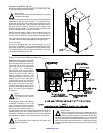
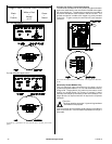
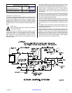
Gas Connections
Inlet connection ..................... 3/4” N.P.T.
Inlet supply size .................... 3/4” Diameter Pipe (min.)
Btu/hr input (per dryer) ......... 160,000 (40,320 kcal/hr)
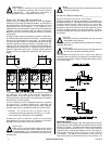
Natural Gas
Regulation is controlled by the dryer’s gas valve’s internal
regulator. Incoming supply pressure must be consistent
between a minimum of 6.0 inches (14.92 mb) and a maximum
of 12.0 inches (29.9 mb) water column (W.C.) pressure.
Liquid Propane (L.P.) Gas
Dryers made for use with L.P. gas have the gas valve’s internal
pressure regulator blocked open so that the gas pressure
must be regulated upstream of the dryer. The pressure
measured at each gas valve pressure tap must be a
consistent 10.5 inches (26.1 mb) water column. There is no
regulator or regulation provided in an L.P. dryer. The water
column pressure must be regulated at the source (L.P. tank)
or an external regulator must be added to each dryer.