


113201-7 Maytag Co. 19
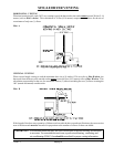
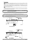
Consistent gas pressure is essential at ALL gas connections. It is recommended that a 3/4-inch (19.05
mm) pipe gas loop be installed in the supply line servicing a bank of dryers. An in-line pressure regulator
must be installed in the gas supply line (header) if the (natural) gas pressure exceeds 12.0 inches (29.9
mb) of water column (W.C.) pressure. (Refer to the illustrations on the previous page.)
NOTE: A water column test pressure of 3.5 inches (8.7 mb) for natural gas and 10.5 inches (26.1 mb)
for liquid propane (L.P.) dryers is required at the gas valve pressure tap of each dryer for
proper and safe operation.
A 1/8” N.P.T. plugged tap, accessible for a test gauge connection, must be installed in the main gas supply
line immediately upstream of each dryer.
IMPORTANT: Pipe joint compounds that resist the action of natural gas and L.P. gas must be used.
IMPORTANT: Test
ALL connections for leaks by brushing on a soapy water solution (liquid
detergent works well).
WARNING:
NEVER TEST FOR LEAKS WITH A FLAME!!!
IMPORTANT: The dryer and its individual shutoff valve must be disconnected from the gas supply
piping system during any pressure testing of that system at test pressures in excess of
1/2 psig (3.5 kPa).
NOTE: The dryer must be isolated from the gas supply piping system by closing its individual manual
shutoff valve during any pressure test of the gas supply system at test pressures equal to or less
than 1/2 psig (3.5 kPa).
H. PREPARATION FOR OPERATION AND START-UP
The following items should be checked before attempting to operate the dryer:
1. Read ALL “CAUTION,” “WARNING,” and “DIRECTION” labels attached to the dryer.
2. Check incoming supply voltage to be sure that it is the same as indicated on the dryer data label.
3. Check to ensure that the dryer is connected to the type of heat or gas indicated on the dryer data label.
4. The sail switch damper assembly was installed and adjusted at the factory prior to shipping. However,
each sail switch adjustment must be checked to ensure that this important safety control is functioning.
5. Check bolts, nuts, screws, terminals, and fittings for tightness.
6. Be sure that ALL gas shutoff valves are in the open position.
7. Check ALL back guard panels and service box covers have been replaced.
8. Make sure the lint coop support bracket has been removed.
9. Check the lint door to ensure that it is closed and secured in place.