


113395-6 Maytag Co. 27
I. PREOPERATIONAL TEST
ALL dryers are thoroughly tested and inspected before leaving the factory. However, a preoperational test
should be performed before the dryer is publicly used. It is possible that adjustments have changed in transit or
due to marginal location (installation) conditions.
1. To start the dryer:
a. Microprocessor Controller (Computer) Dryers (refer to user’s manual included with dryer)
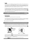
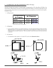
2. Check to ensure that the basket (tumbler) starts in the clockwise (CW) direction. Additionally, check the
direction of the blower motor (impellor/fan) to ensure that blower motor (impellor/fan) rotates in the clockwise
(CW) direction as viewed from the front. If it is, the phasing is correct. If the phasing is incorrect, reverse
two (2) of the leads at L1, L2, or L3 of the power supply connections made to the dryer.
IMPORTANT: Dryer blower motor (impellor/fan) as viewed from the front must turn in the clockwise
(CW) direction, otherwise dryer efficiency will be drastically reduced and premature
component failure can result.
3. Heat Circuit Operational Test
a. Gas Models
1) When the dryer is first started (during initial start-up), the burner has a tendency not to ignite on the
first attempt. This is because the gas supply piping is filled with air, so it may take a few minutes for
this air to be purged.
2) The dryer is equipped with a Direct Spark Ignition (DSI) system, which has internal diagnostics. If
ignition is not established after the first attempt, the heat circuit DSI module will “LOCKOUT” until
it is manually reset. To reset the DSI system, open and close main door and restart dryer.
NOTE: During the purging period, check to be sure that ALL gas shutoff valves are open.
3) Once ignition is established, a gas pressure test should be taken at the gas valve pressure tap of
each dryer to ensure that the water column (W.C.) pressure is correct and consistent.
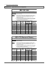
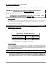
NOTE: Water column pressure requirements (measured at the gas valve pressure tap):
Natural Gas ---------------------- 3.5 inches (8.7 mb) water column.
Liquid Propane (L.P.) Gas ----- 10.5 inches (26.1 mb) water column.
IMPORTANT: There is no regulator provided in an L.P. dryer. The water column pressure must be
regulated at the source (L.P. tank) or an external regulator must be added to each
dryer.
b. Steam Models
Check to ensure that the steam damper is functioning properly.