


36
J. PREOPERATIONAL TESTS
ALL dryers are thoroughly tested and inspected before leaving the factory. However, a preoperational test
should be performed before the dryer is publicly used. It is possible that adjustments have changed in transit or
due to marginal location (installation) conditions.
1. Turn on electric power to the dryer.
a. Open ALL shut-off valves - Gas Models ONLY
2. Refer to the Operating Instructions for starting your particular model dryer.
Gas Dryers
When a gas dryer is first started (during initial start-up), it has a tendency not to ignite on the first ignition
attempt. This is because the gas supply piping is filled with air, so it may take a few minutes for the air to be
purged from the lines.
NOTE: During the purging period, check to be sure that ALL gas shut-off valves are open.
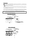
NOTE: Gas Dryers are equipped with a Hot Surface Ignition (HSI) system which has internal
diagnostics. If ignition is not established within three times, the heat circuit in the HSI module
will lock out until it is manually reset. To reset the HSI system, open and close the main door
and restart the dryer.
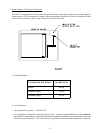
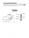
A gas pressure test should be taken at the gas valve pressure tap of each dryer to assure that the water
column pressure (W.C.) is correct and consistent.
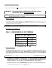
NOTE: Water column pressure requirements (measured at the pressure tap of the gas valve body):
Natural Gas .......... 3.5 - 4.0 -Inches Water Column (W.C.)
L.P. Gas ................ 10.5-11.0 Inches Water Column (W.C.)
IMPORTANT: There is no regulator provided in an L.P. dryer. The water column pressure must be
regulated at the source (L.P. tank), or an external regulator must be added to each
dryer.
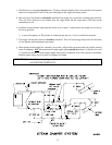
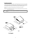
Steam Dryers
Check to insure that steam damper is functioning properly.
The steam damper should not "slam" (open or closed) when it reaches the end of (piston) travel. Additionally,
the steam damper should not bind and/or stop during travel. If either of these conditions occur, the flow
control must be adjusted. Refer to the bottom illustration on page 34 for air adjustment instructions.