


22 American Dryer Corp. 113222-5
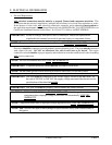
2. Technical Gas Data
a. Gas Specifications
Shaded areas are stated in metric equivalents
* Measured at outlet side of gas valve pressure tap when gas valve is on.
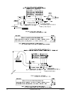
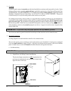
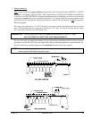
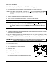
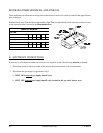
b. Gas Connections:
Inlet connection---- 1/2” N.P.T.
Inlet supply size---- 1/2” Pipe (minimum)
Btu/hr input--------- 60,000 (15,120 kcal/hr)
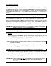
1) Natural Gas
Regulation is controlled by the dryer’s gas valve’s internal regulator. Incoming supply pressure
must be consistent between a minimum of 6.0 inches (14.92 mb) and a maximum of 12.0 inches
(29.9 mb) water column (W.C.) pressure.
2) Liquid Propane (L.P.) Gas
Dryers made for use with L.P. gas have the gas valve’s internal pressure regulator blocked open so
that the gas pressure must be regulated upstream of the dryer. The pressure measured at each gas
valve pressure tap must be a consistent 10.5 inches (26.1 mb) water column. There is no regulator
or regulation provided in an L.P. dryer. The water column pressure must be regulated at the source
(L.P. tank) or an external regulator must be added to each dryer.
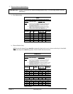
Shaded area is stated in metric equivalent
* Drill Measurement Size (D.M.S.) equivalents are as follows:
Natural Gas.....................#37 = 0.1040” (2.6416 mm).
Liquid Propane Gas .......#52 = 0.0635” (1.6129 mm).
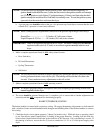
TYPE OF GAS
NATURAL LIQUID PROPANE
Manifold Pressure* 3.5 inches W.C.
8.7 mb
10.5 inches W.C.
26.1 mb
In-Line Pressure 6.0 - 12.0 inches W.C.
14.92 - 29.9 mb
11.0 inches W.C.
27.4 mb
TYPE OF GAS
Liquid Propane
Conversion Kit
Part Number
Btu/hr
Rating
kcal/hr
Rating
Natural Liquid Propane
Qty. D.M.S.*
Part
Number
Qty. D.M.S.*
Part
Number
60,000
15,120
2 #37 140815 2 #52 140800 874058