


15
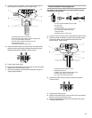
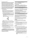
■ Periscope Installation (For use with dryer vent to wall vent
mismatch):
Part Number 4396037 - 0" (0 mm) to 18" (457.2 mm)
mism
atch
Part Number 4396011 - 18" (457.2 mm) to 29" (736.6 mm)
mismatch
Part Number 4396014 - 29" (736.6 mm) to 50" (1270 mm)
mismatch
Special provisions for mobile home installations
The exhaust vent must be securely fastened to a noncombustible
portion of the mobile home structure and must not terminate
beneath the mobile home. Terminate the exhaust vent outside.
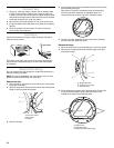
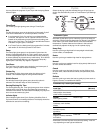
Determine vent path
■ Select the route that will provide the straightest and most
direct path outdoors.
■ Plan the installation to use the fewest number of elbows and
turns.
■ When using elbows or making turns, allow as much room
as possible.
■ Bend vent gradually to avoid kinking.
■ Use the fewest 90° turns possible.
Determine vent length and elbows needed for best
drying performance
■ Use the following Vent system chart to determine type of vent
material and hood combinations acceptable to use.
■ NOTE: Do not use vent runs longer than those specified in
the Vent system chart. Exhaust systems longer than those
specified will:
■ Shorten the life of the dryer.
■ Reduce performance, resulting in longer drying times and
increased energy usage.
The Vent system chart provides venting requirements that will
he
lp to achieve the best drying performance.
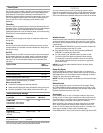
Vent system chart
NOTE: Side and bottom exhaust installations have a 90º turn
inside the dryer. To determine maximum exhaust length, add one
90º turn to the chart.
Number of
90º turns
or elbows
Type of
vent
Box or
Louvered
hoods
Angled
hoods
0 Rigid met
al 64 ft (20 m) 58 ft (17.7 m)
1 Rigid met
al 54 ft (16.5 m) 48 ft (14.6 m)
2 Rigid met
al 44 ft (13.4 m) 38 ft (11.6 m)
3 Rigid metal 35 ft (10.7 m) 29 ft (8.8 m)
4 Rigid metal 27 ft (8.2 m) 21 ft (6.4 m)
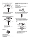
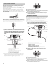
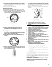
Install Vent System
1. Install exhaust hood. Use caulking compound to seal exterior
wall opening around exhaust hood.
2. Conn
ect vent to exhaust hood. Vent must fit inside exhaust
hood. Secure vent to exhaust hood with 4" (102 mm) clamp.
3. Run vent to dryer location. Use the straightest path possible.
See “Determine vent path” in “Plan Vent System.” Avoid 90º
turns. Use clamps to seal all joints. Do not use duct tape,
screws, or other fastening devices that extend into the
interior of the vent to secure vent. Items sticking through the
vent can catch lint.
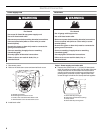
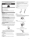
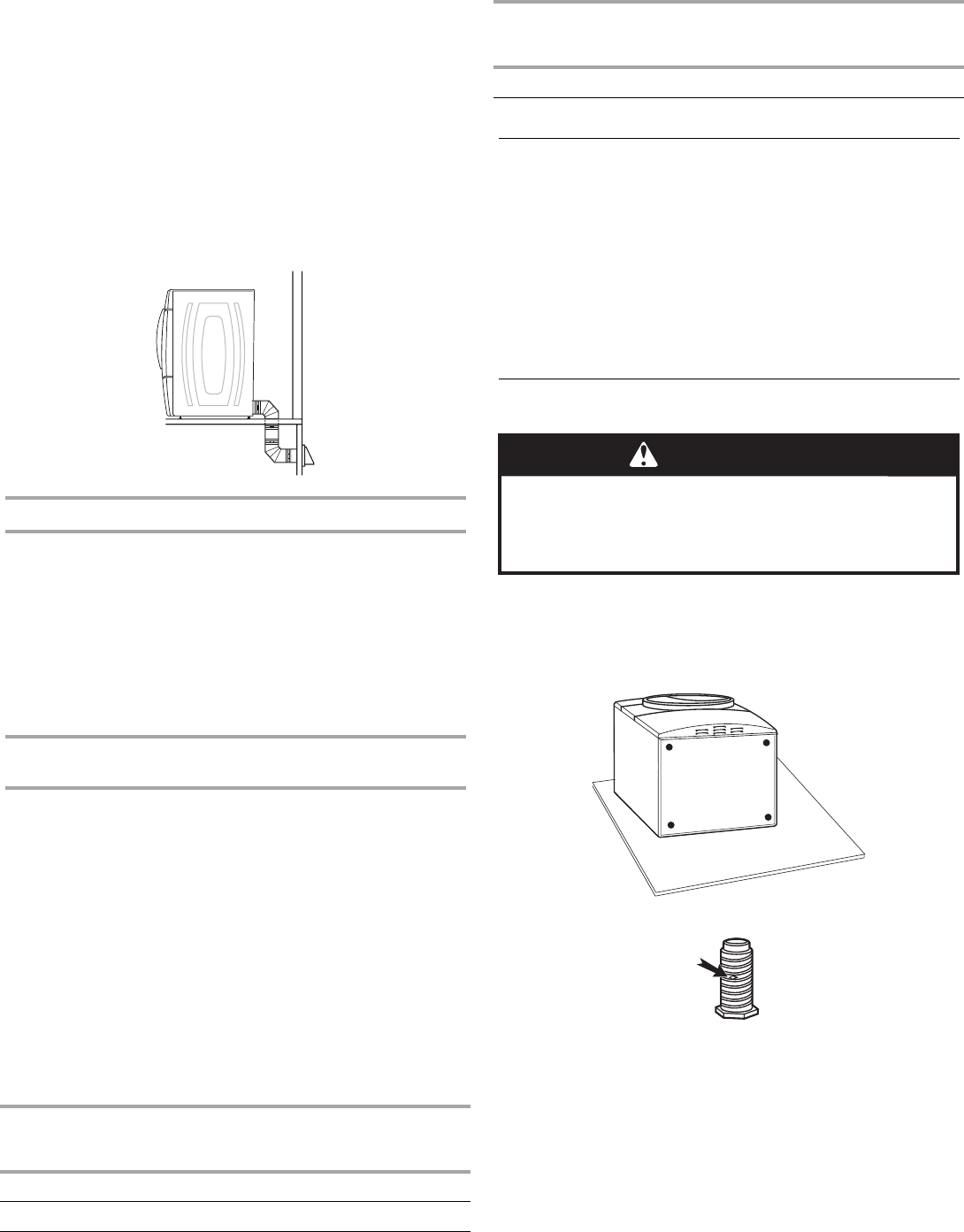
Install Leveling Legs
WARNING
Excessive Weight Hazard
Use two or more people to move and install dryer.
Failure to do so can result in back or other injury.
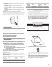
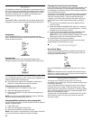
1. To protect the floor, use a large flat piece of cardboard from
the dryer carton. Place cardboard under the entire back edge
of the dryer.
2. Firmly grasp
the body of the dryer (not the console panel).
Gently lay the dryer on the cardboard. See illustration.
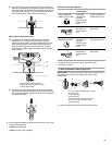
3. Examine the leveling legs. Find the diamond marking.
4. Screw the legs into the leg holes by hand. Use a wrench to
finish turning the legs until the diamond marking is no longer
visible.
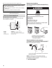
5. Plac
e a carton corner post from dryer packaging under each
of the 2 dryer back corners. Stand the dryer up. Slide the
dryer on the corner posts until it is close to its final location.
Leave enough room to connect the exhaust vent.
Number of
90º turns
or elbows
Type of
vent
Box or
Louvered
hoods
Angled
hoods