


© Copyright, Alliance Laundry Systems LLC – DO NOT COPY or TRANSMIT 506126
14
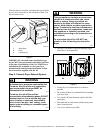
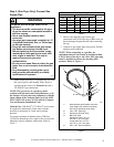
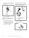
3. Remove the three screws holding the three wires
to the terminal block terminals. Save these
screws. Loosen the strain relief screw and pull
the cord or wires out through the rear of the
dryer.
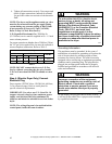
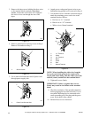
4. Remove ground screw and save for use in Step 6.
Remove wire and use in Step 7.
Figure 13
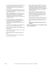
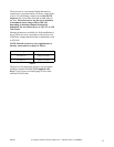
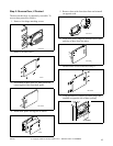
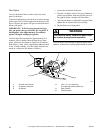
5. Use a strain relief and insert end of power cord
through power supply hole.
Figure 14
6. Attach power cord ground (green) wire to rear
bulkhead using ground screw removed in Step 4.
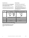
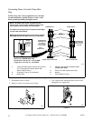
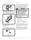
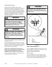
7. Use the three screws from the accessories bag to
attach the remaining power cord wires to the
terminal block as follows:
a. Red wire to “L1” terminal.
b. Black wire to “L2” terminal.
c. White wire to Neutral terminal.
NOTE: When installing the white wire, loop the
free eyelet end of the ground wire (removed in
Step 4) and attach along with the white wire to the
neutral (center) terminal on the terminal block.
8. Tighten all screws firmly.
IMPORTANT: Failure to tighten these screws
firmly may result in wire failure at the terminal
block.
9. Check the continuity of the ground connection
before plugging the cord into an outlet. Use an
acceptable indicating device connected to the
center grounding pin of the plug and the green
screw on the back of the cabinet.
10. Reinstall access cover and screw.
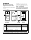
D696I
Figure 12
D697I
1 Ground Screw
D698I
1 Power Cord Ground Wire
D697I
1
D698I
1
DRY522N
1 “L1” Terminal
2 White
3 “L2” Terminal
4 Black
5 Green
6 Red
7 Neutral Terminal
Figure 15
1
7
2
3
4
5
6