


© Copyright, Alliance Laundry Systems LLC – DO NOT COPY or TRANSMIT
Operation
70283501
14
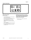
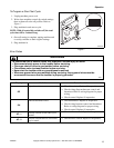
Ignition Control Operation
Power Up
After 24 VAC is applied to the ignition control pins
24V and GND, the Diagnostic LED on the ignition
control will turn orange/yellow. If a fault is detected
the ignition control will enter Lockout Mode. If no
faults are detected, the Diagnostic LED will turn
Green and the ignition control will enter Standby
Mode.
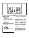
Standby Mode
While in Standby Mode, the ignition control will
continually monitor the system for faults. Once
24VAC is applied to terminals TH and GND on the
control, the ignition control will enter Start Up Mode.
Start Up Mode
During Start Up Mode, the ignition control will
monitor the system for faults and begin the ignition
sequence. If no faults are present, the ignition control
will begin the ignition sequence by entering an 18
second waiting period. During this time the Green
LED on the ignition control will switch between Red
and Green, before maintaining a Green color.
After the waiting period, the ignition control will turn
on the igniter and gas valve. The igniter will remain on
until a flame is sensed, or up to 10 seconds.
Once a flame has been sensed the ignition control will
stop sparking, the gas valve will remain on and
ignition control will enter Run Mode.
If a flame is not sensed, the ignition control will then
begin two additional retrials for ignition. The ignition
control will re-enter the 18 seconds waiting period
before the ignition control makes another attempt at
ignition. If the three attempts at ignition fail, the
ignition control will enter Lockout Mode.
Run Mode
While in Run Mode the ignition control leaves the gas
valve on, monitors the flame signal, and leaves the
igniter off.
If a flame signal is lost during Run Mode, one
additional retrial for ignition will take place within one
second. The ignition control will restore the spark for
approximately 10 seconds. If the ignition re-attempt
fails, the ignition control will enter Lockout Mode.
The ignition control will remain in Run Mode until
24VAC is removed from terminals TH and GND on
the control.
Termination of Flame
The flame will go out when power is removed from
ignition control. The ignition control will turn off the
gas valve and enter Standby Mode.
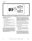
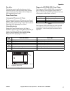
Lockout Mode
When Lockout Mode is entered, the ignition control
will remove power to the gas valve, the igniter will
turn off, the Lockout/Reset Light will turn on, and the
Diagnostic LED will display the appropriate Error
Code.
Lockout Manual Reset
Lockout Mode is cleared by pressing an external reset
switch for three seconds. The ignition control will
clear all error codes and enter Standby Mode. During
Lockout Manual Reset, the Diagnostic LED on the
ignition control flashes red and orange, and the Reset
Light remains on until the ignition control is reset.
After the Reset Light turns off, stop pressing the
switch. Holding the reset for three seconds after
lockout has been cleared will cause a fault and result in
entering Lockout Mode again.
System Tests
The following system tests are performed during
normal operation. System tests are performed at a
minimum of every 24 hours.
Low Voltage Detection
If the voltage between terminals TH and GND on the
control is below 18.75VAC +/- 0.75VAC for more than
3 seconds the ignition control will turn off the gas
valve and will not attempt to spark. The Diagnostic
LED will display Error Code 5. The ignition control
will not enter Lockout Mode if a low voltage condition
is detected, but will enter Standby Mode and wait for
the low voltage condition to be cleared.
If the voltage between terminals TH and GND on the
control rises above 19.75VAC +/- 0.1VAC for at least
3 seconds, the ignition control will then enter Start Up
Mode.
Low Voltage Detection test is disabled during Run
Mode.