


30
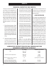
HEATER PARTS REMOVAL AND INSTALLATION
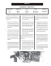
b. Use a dependable brand of
high temperature pipe caulking
compound when assembling gas
connections. Apply only a light
coating onto male threaded end
of fittings.
c. Solenoid valves and gas regula-
tors are directional and must be
properly installed. Do not attempt
to connect gas solenoid valve by
applying force to the valve core
stem as it may ruin the unit.
d. Make sure all electrical wires are
properly connected. Refer to wiring
diagrams.
SERVICE
b. Disconnect gas solenoid valve
coils. Be sure to mark which one
goes where.
c. Lift pipe (with orifice, solenoid
valve and other parts attached),
straight up and remove from fan/
heater housing. Orifice and other
parts can now be removed from
pipe train, if desired.
5. Reassemble: To reassemble
parts, reverse the disassembly pro-
cedure and check the following:
a. Make sure all parts are thoroughly
cleaned and open.
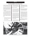
Most of the heater parts can be re-
moved by simply identifying any at-
tached wiring, and then disconnect-
ing the obvious mounting parts.
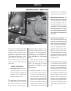
1. Flame sensor: Disconnect the
wire connector, and unscrew the
flame sensor out of its mount-
ing bracket.
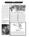
2. Gas Solenoid valve coil(s):
Unsnap either the plastic cap,
or the metal clip on the gas valve,
and slide the housing and coil
off the valve stem and body. Do
not energize the coil when it is
removed, as the coil may be
come damaged due to exces-
sive current flow.
3. Regulator and gas solenoid
valve(s): The gas regulator and so-
lenoid valve(s) are directional and
must be connected as indicated by
the markings near the port open-
ings. Make sure gas is shut off and
purged from the system before re-
moving parts.
Note: When installing a liquid
gas solenoid valve on LP models,
do not over tighten the connection
into the inlet side, as the inlet orifice
may become partially blocked.
4. Main Gas Orifice: With fuel shut
off and gas purged from system,
proceed as follows:
a. Disconnect the plumbing sup-
port brackets from the pipe train.
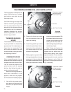
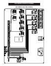
1
3
3
2
4
5
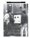
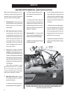
This view of the dryer heater shows 1-high pressure gas solenoid, 2-low
pressure gas solenoid, 3-gas solenoid valves, 4-gas regulator and 5-
vaporizer adjustment bracket