


28
SERVICE
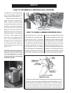
FAN PROPELLOR REMOVAL AND INSTALLATION
The fan propellor is secured to the
motor shaft by the use of a taper-
lock bushing, motor shaft key and
three cap screws.
CAUTION: Although the taper-lock
method of retaining the propellor
onto the motor shaft is simple, it is
essential that the following points be
read carefully and fully understood.
Improper installation can cause a
loose flying propellor, and result in
serious injury or death.
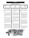
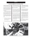
Capscrews installed
through threaded
holes of bushing
Split Taper Bushing
Fan Hub
Key
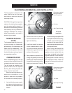
THREADED BUSHING
HOLES
The threaded holes within the bush-
ing are provided for disassembly
purposes only. Do not attempt to use
these holes for reassembly. They
will not allow the parts to lock onto
the shaft thereby causing a hazard-
ous operating condition.
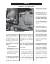
remove bushing and propellor. With
the propellor free from the bushing,
a wheel can be used to pull the
bushing off of the motor shaft. Re-
attach bushing onto propellor to pre-
vent the loss of parts.
Note: During manufacture the
propellor and bushing are balanced
together and are marked with two
small dots to identify their original
alignment position. Check the bush-
ing and propellor to make sure they
have alignment marks. Mark the
alignment of the propellor and bush-
ing, if necessary.
Capscrews installed
through threaded
holes of bushing
Split Taper Bushing
Fan Hub
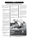
Fan blade
installation
Fan blade
removal
When reassembling parts, the cap
screws must be installed through the
untapped clearance holes as shown.
This will cause the propellor to be
pulled forward onto the tapered
bushing, thus locking the parts se-
curely onto the motor shaft.
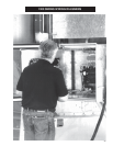
When fan servicing requires re-
moval and installation of the
propellor, make sure the propellor
is removed and reinstalled properly.
1. Lock out the fan power supply,
and remove the fan guard and
the venturi, as required on some
models.
CLEARANCE HOLES
2. Remove the three cap screws
from the clearance holes in the
taper-lock bushing.
3. Install two grade 5 cap screws
into the threaded holes in bush-
ing, and turn them by hand until
they bottom against the front
surface of the propellor.
4. Block propellor to prevent it from
turning, and gradually turn the cap
screws (up to 1/4 turn at a time) until
the propellor breaks loose from the
bushing and motor shaft. Carefully