


23
IMPORTANT: The dryer must be connected to the electric supply shown on the data label. In the
case of 208 VAC or 240 VAC, the supply voltage must match the electric service
specifications of the data label exactly.
WARNING: 208 VAC and 240 VAC
ARE NOT THE SAME. Any damage done to dryer
components due to improper voltage connections will automatically
VOID THE
WARRANTY.
NOTE: ADC reserves the right to make changes in specifications at any time without notice or
obligation.
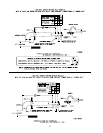
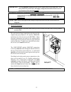
3. Electrical Connections
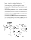
NOTE: A wire diagram is included with each dryer and is affixed to the back side of the top control
(access) door.
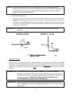
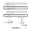
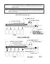
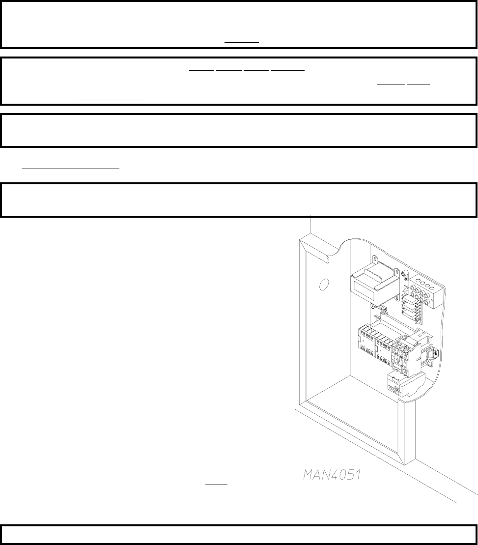
The only electrical input connections to the dryer are the
3-phase (3ø) power leads (L1, L2, and L3), GROUND,
and in the case of 4 wire service, the NEUTRAL. These
electrical connections are made at the terminal block
located in the service/relay box at the rear, upper left hand
corner of the dryer. To gain access into this service box,
the service cover must be removed.
The “LINE POWER” and the “GROUND” connections
to the dryer must be made through the knockout hole at
the top of the electric service/relay box. A strain relief
must be used where the line power ground wires go into
the electric service/relay box.
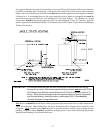
Providing local codes permit, power connections to the
dryer can be made by use of a flexible underwriters
laboratory (U.L.) listed power cord/pigtail (wire must
conform to ratings of the dryer), or the dryer can be hard
wired directly to the service breaker. In ALL cases, a
strain relief must be used where the wire(s) enter the
dryer electrical service (relay) box.
NOTE: A CIRCUIT SERVICING EACH DRYER MUST BE PROVIDED.