14
MV 6 Y G W
O B
RC RH
HP
MV W RH RC G Y O B 6
RC
G
Y
5
2
C
1
D
43
L
M
KJ
I
F G
WIRING DIAGRAMSWIRING DIAGRAMS
WIRING DIAGRAMSWIRING DIAGRAMS
WIRING DIAGRAMS
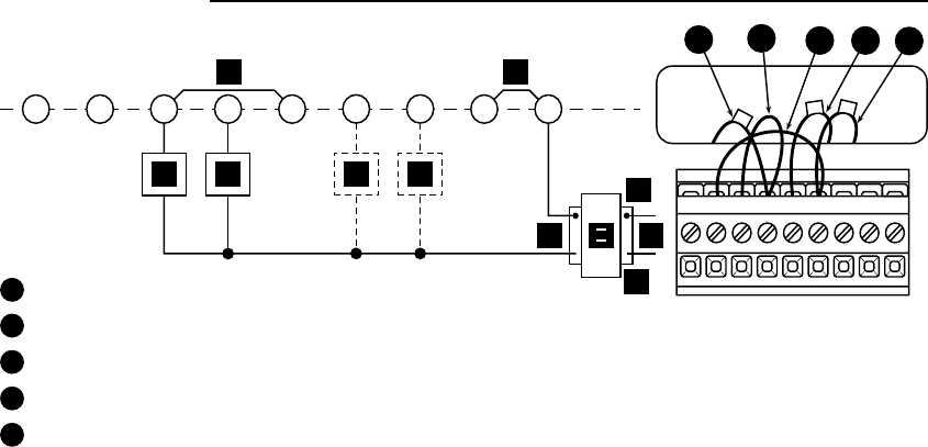
Figure 8. Typical wiring diagram for single stage heat pump, four-wire, single transformer systemFigure 8. Typical wiring diagram for single stage heat pump, four-wire, single transformer system
Figure 8. Typical wiring diagram for single stage heat pump, four-wire, single transformer systemFigure 8. Typical wiring diagram for single stage heat pump, four-wire, single transformer system
Figure 8. Typical wiring diagram for single stage heat pump, four-wire, single transformer system
1
From heating system
2
Red jumper wire (provided)
3
Field-installed jumper wire
4
From fan relay
5
From cooling system
NOTE: Ensure that RED RH/RC jumper wire (provided with thermostat) is
connected between thermostat’s RH and RC terminals for proper
operation with this system.
See page 10 for letter identification.


