Specifications and Requirements iTherm
®
280 Programmer’s Guide
Page 30 Rev C 28-07764
Communications Interface
Parallel Interface
Your printer features two parallel interfaces:
• An IEEE 1284-A 25-pin, D-shell connector, with pin-outs that interface to a
standard IBM PC parallel printer interface with a one-to-one cable.
• An IEEE 1284-B, which is a standard Centronics 36-pin connector.
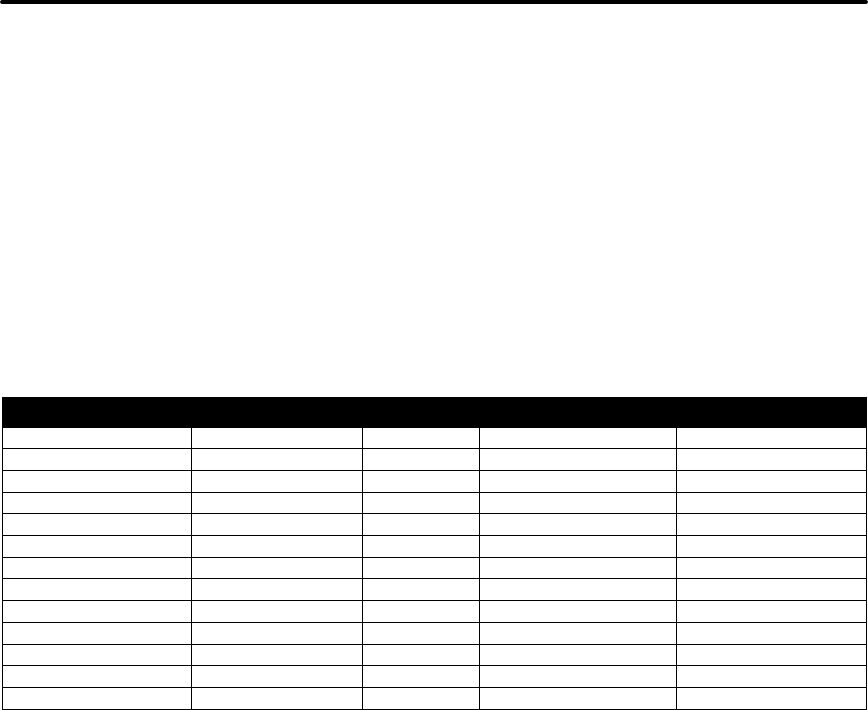
Both interface cards provide a dual cash drawer interface. The following table lists
interface signals and corresponding pins.
25-pin Connector 36-pin Connector Signal Description Direction
Pin 1 Pin 1 STROBE Clock data to printer Host to Printer
Pins 2-9 Pins 2-9 D0 - D7 Data Host to Printer
Pin 10 Pin 10 ACK\ Printer accepted data Printer to Host
Pin 11 Pin 11 BUSY Printer busy Printer to Host
Pin 12 Pin 12 PE Paper Out/Status Printer to Host
Pin 13 Pin 13 SLCT Printer selected Printer to Host
Pin 14 Pin 14 AUTOFD Autofeed paper Host to Printer
Pin 15 Pin 32 FAULT\ Printer error Printer to Host
Pin 16 Pin 31 INIT\ Initialize printer Host to Printer
Pin 17 Pin 36 SLIN Select printer Host to Printer
Pin 17 FG Frame ground Printer to Host
- Pin 18 +5V Peripheral logic high Printer to Host
Pins 18-25 Pins 16, 19-30 GND Ground
Table 4 Parallel Interface Pin-outs
Signal Levels
Voltage levels 0 V and +5 V (nominal)
Logic levels
Logic one
Driver +2.4 V to +5 V
Receiver +2.0 V to +5 V
Logic zero
Driver 0 V to +0.4 V
Receiver 0 V to +0.8 V
Current requirements
Logic one Source 0.25 ma at +2.4 V
Logic zero Sink 16 ma
Line termination
Data and control 3.3k ohm to +5 V
Strobe 1.2k ohm to +5 V