TMP92CM22
2007-02-16
92CM22-137
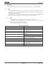
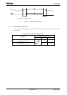
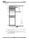
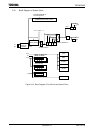
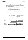
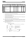
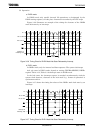
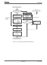
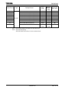
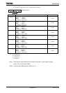
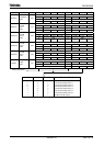
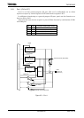
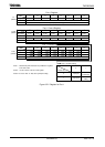
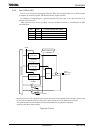
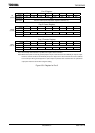
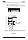
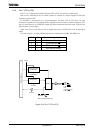
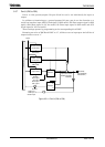
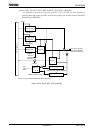
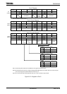
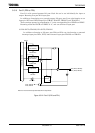
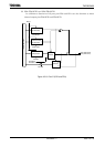
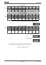
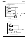
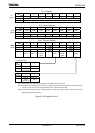
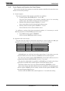
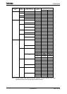
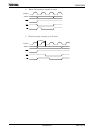
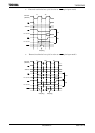
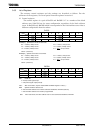
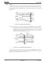
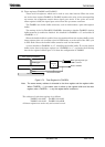
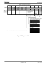
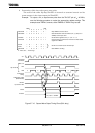
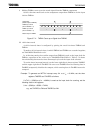
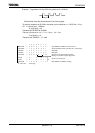
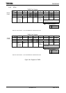
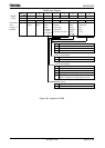
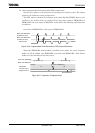
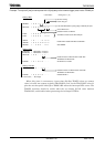
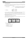
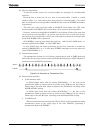
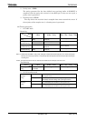
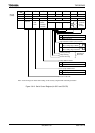
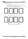
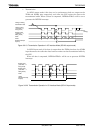
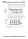
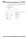
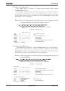
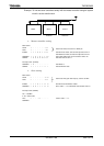
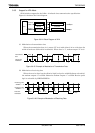
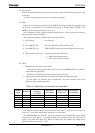
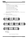
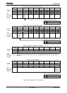
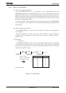
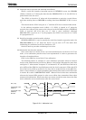
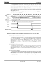
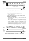
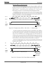
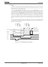
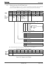
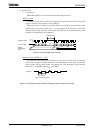
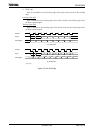
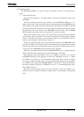
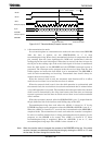
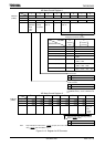
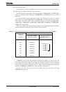
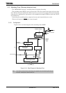
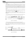
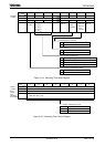
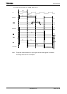
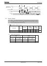
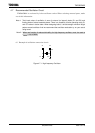
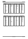
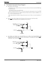
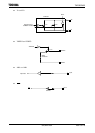
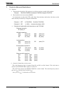
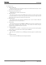
Example: To output a 2 [ms] one-shot pulse with a 3 [ms] delay to the external trigger pulse via the TB1IN0 pin.
* Clock state : Clock gear 1/1 (fc)
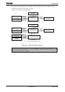
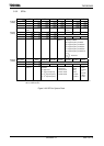
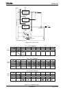
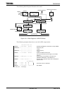
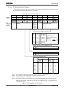
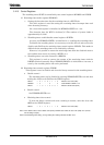
Setting in Main
Set free running.
Count using φT1.
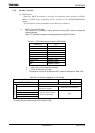
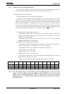
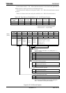
TB1MOD ← X X 1 0 1 001
Load into TB1CP0H/L by rising edge of TB1IN0 pin input.
TB1FFCR ← X X 0 0 0 010
Clear TB1FF0 to 0.
Disable inversion of TB1FF0.
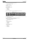
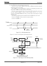
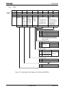
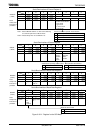
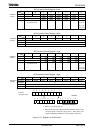
PDCR ← X X X X − 1 − −
PDFC ← X X X X − 1XX
Set PD2 to function as the TB1OUT0 pin.
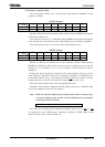
INTE45 ← X − − − X 100
INTETB1 ← X 0 0 0 X 000
Enable INT4. Disable INTTB10 and INTTB11.
TB1RUN ← − 0 X X − 1X1 Start TMRB0.
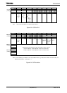
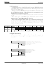
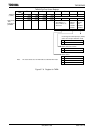
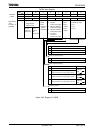
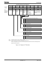
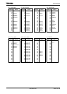
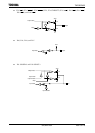
Setting in INT4
TB1RG0H/L ← TB1CP0H/L + 3 ms/φT1
TB1RG1H/L ← TB1RG0H/L + 2 ms/φT1
TB1FFCR ← X X − − 1 1 − −
Enable inversion of TB1FF0 when match with
TB1RG0G/L or TB1RG1G/L.
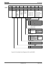
INTETB1 ← X 1 0 0 X − − − Set INTTB11 to enable.
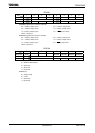
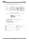
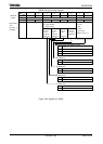
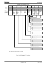
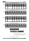
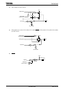
Setting in INTTB11
TB1FFCR ← X X − − 0 0 − −
Disable inversion of TB1FF0 when match with
TB1RG0H/L or TB1RG1H/L.
INTETB1 ← X 0 0 0 X − − − Disable INTTB11.
X : Don’t care, − : No change
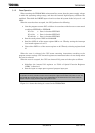
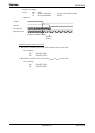
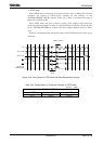
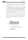
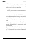
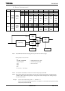
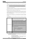
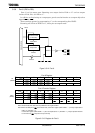
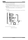
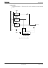
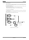
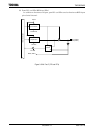
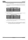
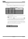
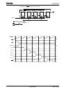
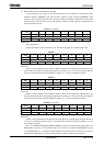
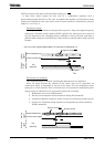
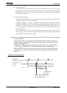
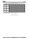
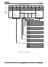
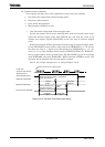
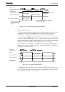
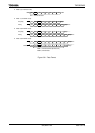
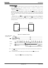
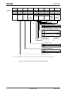
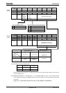
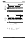
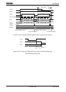
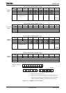
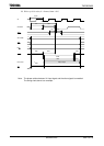
When delay time is unnecessary, invert timer flip-flop TB1FF0 when up counter
value is loaded into capture register (TB1CP0H/L), and set the TB1CP0H/L value (c)
plus the one-shot pulse width (p) to TB0RG1H/L when the interrupt INT4 occurs. The
TB1FF0 inversion should be enable when the up counter (UC12) value matches
TB1RG1H/L, and disabled when generating the interrupt INTTB11.