MJ-1103/1104 © 2008, 2009 TOSHIBA TEC CORPORATION All rights reserved
DISASSEMBLY AND INSTALLATION
4 - 56
[I] Upper exit roller / Upper exit roller guide
(1) Take off the rear upper cover.
P.4-6 "[G] Rear cover"
(2) Take off the control panel unit.
P.4-3 "[D] Control panel unit"
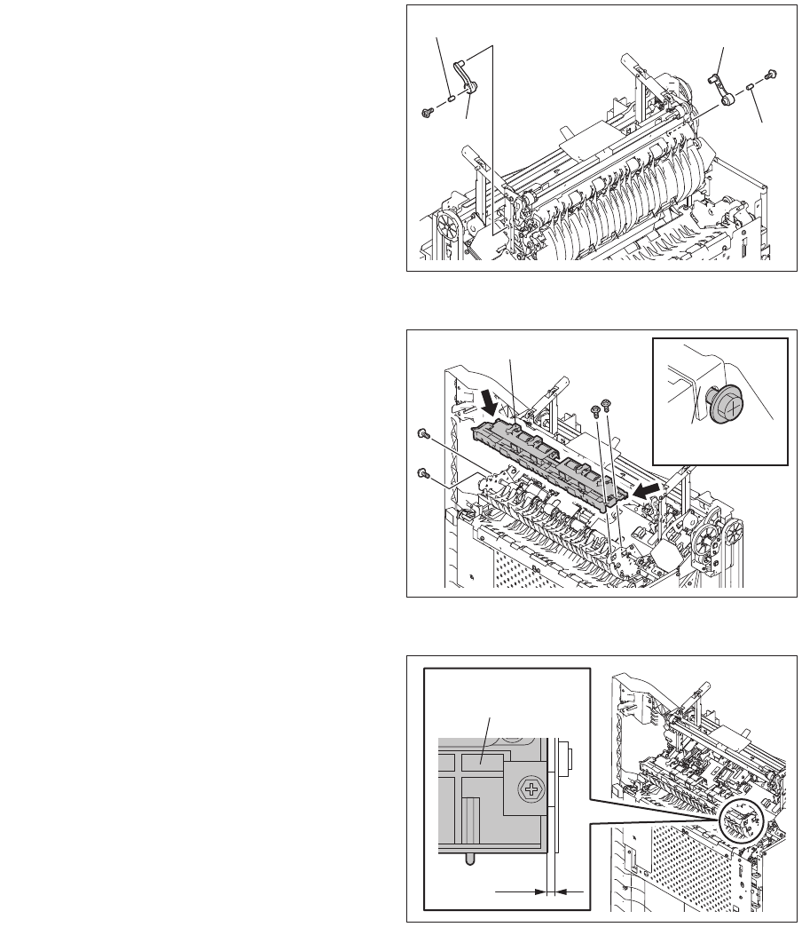
(3) Remove 2 screws, and then take off the front
and rear stays and 2 spacers.
Be careful not to damage the harness con-
nected to the stationary tray transport
guides.
Fig. 4-156
(4) Loosen 2 screws each for the front and rear
stationary tray discharge brush.
(5) Remove 4 screws and take off the front and
rear stationary tray transport guides.
Be careful not to damage the harness of
entrance sensor.
When installing the front and rear stationary
tray transport guides, fix them at the posi-
tions where the gap between the trailing
edges of the guides and the frame is 1 mm.
Check if the flap and the upper exit roller
move smoothly after screws are tightened.
Fig. 4-157
Fig. 4-158
Stationary tray transport guide
Stationary tray
discharge brush
1mm
Stationary tray
transport guide


