Chapter 2: Installation
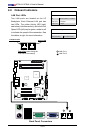
2-23
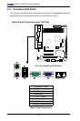
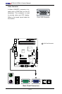
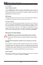
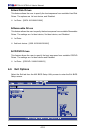
JF1
J13
JL1
R52
R53
JPL1
JPL2
FAN3
FAN1
FAN_NB
41
FAN2
J3
J51
J46
JP5
JP4
BT1
JBT1
TP_ICH3
Tested to Comply
With FCC Standards
FOR HOME OR OFFICE USE
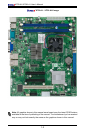
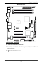
X7SLA-H
DESIGNED IN USA
NIC
I-SATA3
I-SATA2
I-SATA1
I-SATA0
SLOT7 PCI-E X4 in X8
SLOT6 PCI-E X8
USB2/3
COM2
USB4/5
USB6
JBT1:CMOS CLEAR
IDE
SLOT5 PCI 33MHZ
1-2:ENABLE
2-3:DISABLE
JPL1-2:LAN1/2
INTRUSION
JL1:CHASSIS
LAN2
LAN1
VGA
COM1
X
LED
PWRHDD
NIC
/FF
OHRSTPWR ON
1
JF1
DIMM1A
DIMM1B
JPW1
JPW2 for Device Power Only
KB/MOUSE
USB7
USB0/1
CPU
945GC
ICH7R
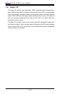
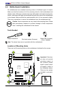
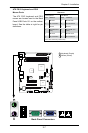
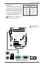
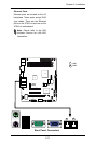
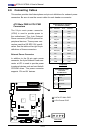
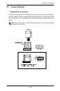
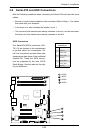
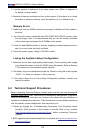
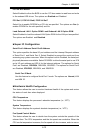
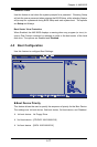
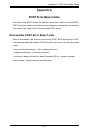
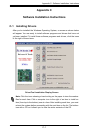
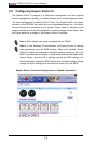
2-9 Serial ATA and HDD Connections
Note the following conditions when connecting the Serial ATA and hard disk drive
cables:
• Be sure to use the correct cable for each connector. Refer to Page 1-1 for cables
that came with your shipment.
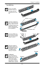
• A red mark on a wire indicates the location of pin 1.
• The connector with twisted wires always connects to drive A, and the connector
that does not have twisted wires always connects to drive B.
A
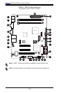
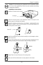
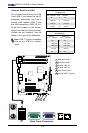
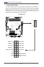
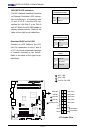
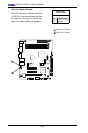
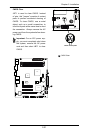
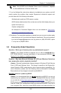
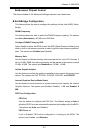
SATA Connectors
Four Serial ATA (SATA) connectors (I-SA-
TA 0~3) are located on the motherboard
to provide serial link connections. Se-
rial Link connections provide faster data
transmission than those of the traditional
Parallel ATA. These four SATA connec-
tors are supported by the Intel ICH7R
South Bridge. See the table on the right
for pin denitions.
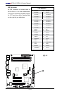
SATA Connectors
PinDenitions
Pin# Signal
1 Ground
2 SATA_TXP
3 SATA_TXN
4 Ground
5 SATA_RXN
6 SATA_RXP
7 Ground
B
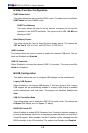
I-SATA0
I-SATA1
I-SATA2
I-SATA3
C
D
A
B
C
D