Chapter 2: Installation
2-19
G
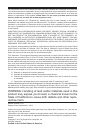
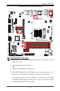
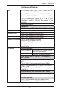
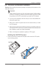
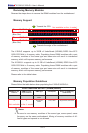
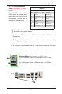
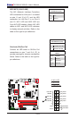
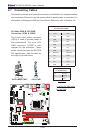
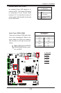
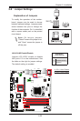
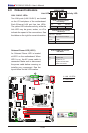
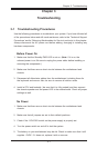
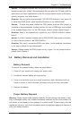
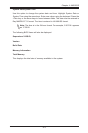
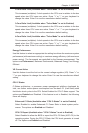
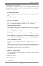
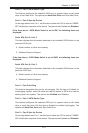
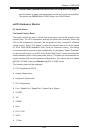
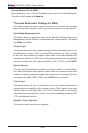
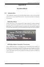
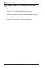
Ethernet Ports
Two Gigabit Ethernet ports (LAN1/
LAN2) are located next to the
HD Audio Connector on the I/O
Backpanel to provide network con-
nections. These ports accept RJ45
type cables.
Note: Please refer to the
LED Indicator Section for
LAN LED information.
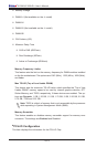
LAN Ports
Pin Denition
Pin# Denition
1 P2V5SB 10 SGND
2 TD0+ 11 Act LED
3 TD0- 12 P3V3SB
4 TD1+ 13 Link 100 LED
(Green, +3V3SB)
5 TD1- 14 Link 1000 LED
(Yellow, +3V3SB)
6 TD2+ 15 Ground
7 TD2- 16 Ground
8 TD3+ 17 Ground
9 TD3- 88 Ground
(NC: No Connection)
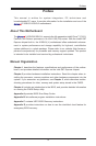
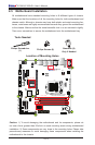
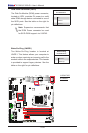
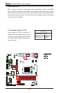
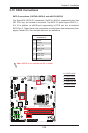
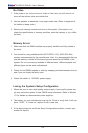
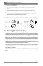
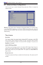
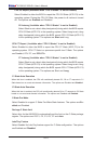
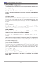
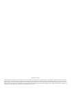
A. LAN1
B. LAN2
C. SPDIF_Out
D. Surround_Out
E. CEN/LFE_Out
F. Mic_In
G. Line-Out
H. Line_In
E
C
D
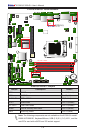
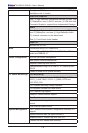
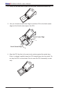
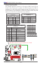
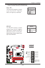
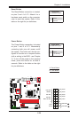
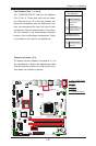
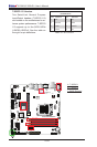
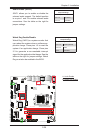
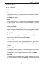
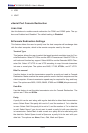
Back Panel High Denition
Audio (HD Audio)
This motherboard features a 7.1+2
Channel High Definition Audio
(HDA) codec that provides 10
DAC channels. The HD Audio con-
nections simultaneously supports
multiple-streaming 7.1 sound play-
back with 2 channels of independent
stereo output through the front panel
stereo out for front, rear, center
and subwoofer speakers. Use the
Advanced software included in the
CD-ROM with your motherboard to
enable this function.
(BP) HD Audio
Conn# Signal
A
SPDIF_Out
B
Surround_Out
C
CEN/LFE_Out
D
Mic_In
E
Line_Out
F
Line_In
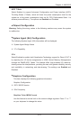
HD Audio
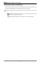
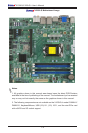
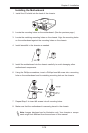
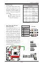
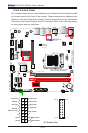
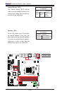
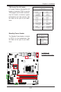
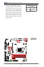
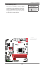
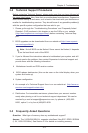
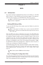
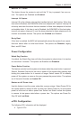
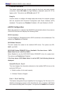
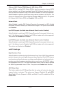
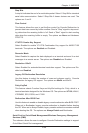
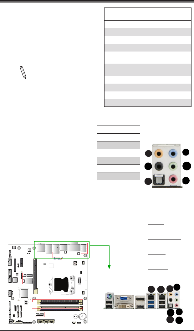
X10SLQ (-L)
Rev. 1.00
MAC CODE
BAR CODE
BIOS
LICENSE
JSD1
JBT1
SP1
JITP1
LED1
LED2
LED3
T-SGPIO1
T-SGPIO2
COM1
COM2
COM3
COM4
JD1
FAN3
FAN2
FAN1
FAN4
JP2
JP1
JLED1
JWD1
JPL2
JPL1
JPAC1
JI2C1 JI2C2
JP5
JP4
JP3
JL1
JWOR1
JHD_AC1
I-SATA2
I-SATA1
I-SATA3
I-SATA0
I-SATA4
JTPM1
JF1
JPW2
USB10/11(3.0)
AUDIO FP
USB6/7
USB8/9
SLOT4 PCI-E 2.0 X4
SLOT5 PCI-E 2.0 X1
HD AUDIO
SLOT7 PCI-E 3.0 X16
USB4/5
LAN2
USB2/3(3.0)
LAN1
HDMI/DP
ALWAYS POPULATE BLUE SOCKET FIRST
UNB NON-ECC DDR3 DIMM REQUIRED
VGA/DVI
KB/MOUSE
USB0/1
CPU FAN
DIMMA1
DIMMA2
DIMMB1
DIMMB2
Battery
JPW1
BIOS
Intel PCH
JBR1
JPME1
JVR1
Not On “-L
Model”
Not On “-L Model”
Not On “-L Model”
Not On “-L
Model”
CPU
Not On “-L Model”
Not On “-L Model”
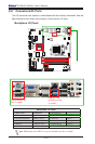
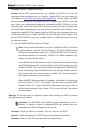
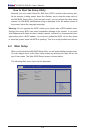
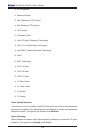
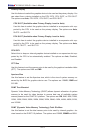
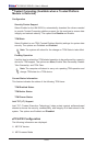
A
E
B
H
G
C
D
H