2-10
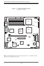
SUPER X5DL8-GG/X5DLR-8G2+/X5DLR-8G2 User’s Manual
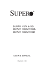
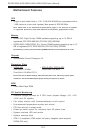
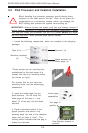
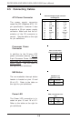
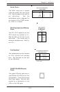
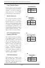
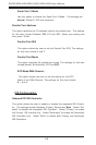
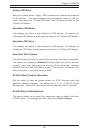
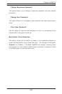
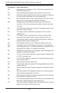
PWR_ON
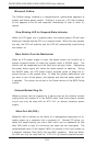
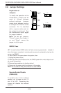
The PWR_ON connection is lo-
cated on pins 1 and 2 of JF1. Mo-
mentarily contacting both pins will
power on/off the system. This
button can also be configured to
function as a suspend button (see
the Power Button Mode setting in
BIOS). To turn off the power
when set to suspend mode, de-
press the button for at least 4
seconds. Refer to the table on the
right for pin definitions.
Pin
Number
1
2
Definition
PW_ON
Ground
PWR_ON Connector
Pin Definitions
(JF1)
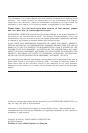
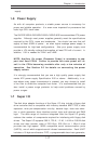
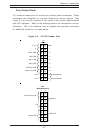
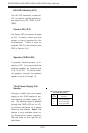
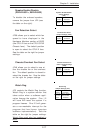
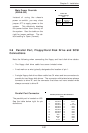
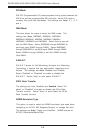
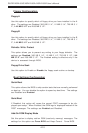
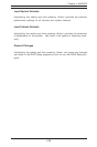
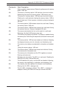
Universal Serial Bus
(USB0/1)
Two Universal Serial Bus ports
are located beside the keyboard/
mouse ports. USB0 is the bottom
connector and USB1 is the top
connector. See the table on the
right for pin definitions.
Universal Serial Bus Pin Definitions
Pin
Number Definition
1+5V
2P0-
3P0+
4 Ground
5 N/A
Pin
Number Definition
1+5V
2P0-
3P0+
4 Ground
5Key
USB0
USB1
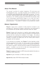
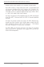
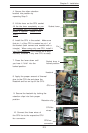
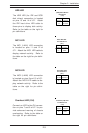
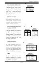
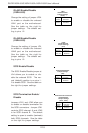
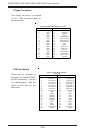
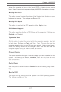
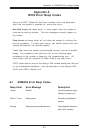
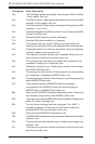
Power Fail LED
The Power Fail LED connection is
located on pins 5 and 6 of JF1.
Refer to the table on the right for
pin definitions.
Power Fail LED Pin
Definitions
(JF1)
Pin
Number
5
6
Definition
Control
GND
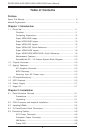
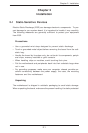
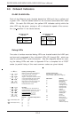
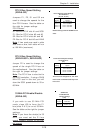
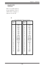
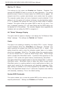
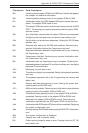
Reset
The Reset connection is located
on pins 3 and 4 of JF1. Attach it
to the hardware reset switch on
the computer case. Refer to the
table on the right for pin defini-
tions.
Pin
Number
3
4
Definition
Reset
Ground
Reset Pin
Definitions
(JF1)