2-18
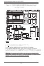
SUPER i2DMR-8G2/i2DMR-iG2 User's Manual
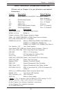
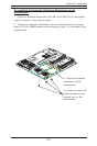
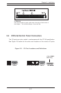
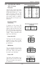
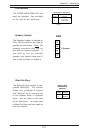
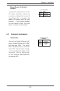
Power Fault
Connect a cable from your power
supply to the U62 header to pro-
vide warning of power supply fail-
ure. This warning signal is
passed through the PWR_LED pin
on U66 to indicate of a power fail-
ure on the chassis. See the table
on the right for pin definitions.
Note: This feature is only available when using
redundant Supermicro power supplies.
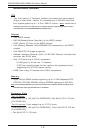
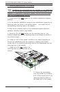
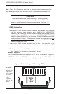
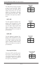
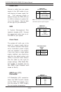
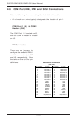
SMB
A System Management Bus
header is located at J22. Connect
the appropriate cable here to uti-
lize SMB on your system.
Power Fault
Pin Definitions (U62)
Pin
Number
1
2
3
4
Definition
P/S 1 Fail Signal
P/S 2 Fail Signal
P/S 3 Fail Signal
Reset (from MB)
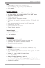
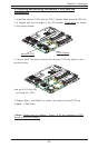
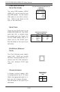
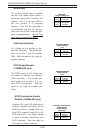
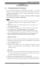
Alarm Reset
The system will notify you in the
event of a power supply failure.
This feature assumes that Super-
micro redundant power supply
units are installed in the chassis.
If you only have a single power
supply installed, you should dis-
able this (the default setting) with
(CN5) to prevent false alarms.
See the table on the right for
jumper settings. (The Alarm Re-
set header is located next to
the PWR Fault header and
close to Fan3.)
SMB Header
Pin Definitions (J22)
Pin
Number
1
2
3
4
Definition
Data
Ground
Clock
No Connection
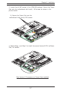
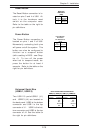
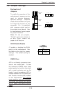
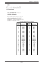
SMB Power (I
2
C)
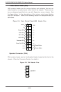
Connector
I
2
C Connector (J27), located be-
tween the PWR ForceOn Header
and the PWR Fault header, moni-
tors the status of PWR Supply,
Fan and system temperature.
SMB PWR
Pin Definitions (J27)
Pin #
1
2
3
4
5
Definition
Clock
Data
N/A
N/A
N/A
Jumper
Position
Open
Closed
Definition
Enabled
Disabled
Alarm Reset Jumper
Settings
(CN5)