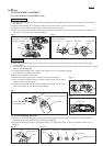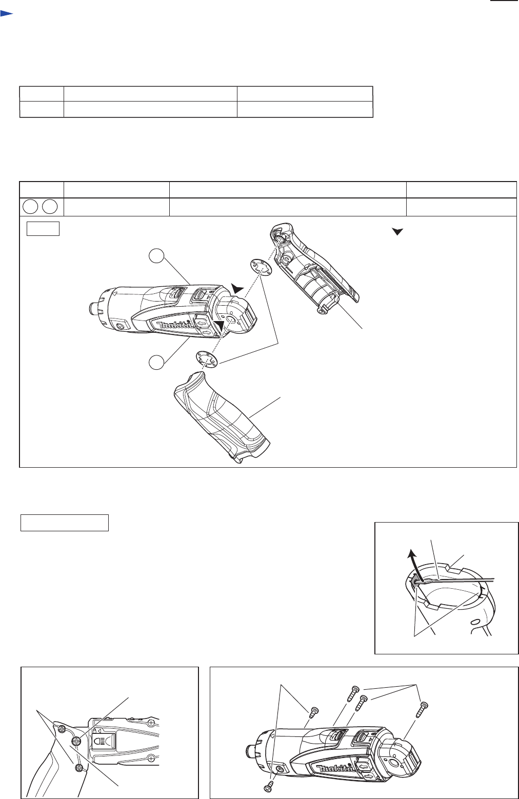
(1) Remove two Set plates from Handle set as follows:
Insert a small slotted screwdriver through the punched hole of set plate and move
Set plate in the direction of the arrow using the screwdriver while
pushing Set plate against Handle set. (Fig.2)
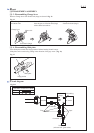
(2) Handle set can be removed from Motor housing by removing two Bind 3x14
tapping screws and one 4x25 tapping screw from Handle set. (Fig. 3)
(3) Separate Housing R and Housing L by removing three Bind 3x14 tapping screws
and two Bind PT3x8 tapping screws. (Fig. 4)
Repair
P 2
/ 5
[3] DISASSEMBLY/ASSEMBLY
[3]-1. DC motor, Gear assembly
Fig. 3 Fig. 4
DISASSEMBLING
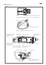
[2] LUBRICATION
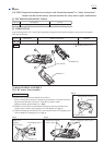
Apply Makita grease N No.2 to the following portions designated with the black triangle to protect parts and product
from unusual abrasion.
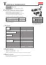
[1] NECESSARY REPAIRING TOOLS
CAUTION: Repair the machine in accordance with “Instruction manual” or “Safety instructions”.
Remove the bit and the battery f
rom the machine for safety before repair/ maintenance.
Fig. 1
DescriptionCode No. Use for
Item No. Description Portion to lubricate Amount
a littleMotor housing R and L
Lock washer
Handle (L)
Handle (R)
Each hinge portion that contacts Lock washer
1R362 Removing/ Installing Bit sleeve
Makita grease N No.2
11
11
26
26
Bind 3x14
tapping
screws (2pcs.)
Fig. 2
Bind 3x14 tapping screws (3pcs.)Bind PT3x8 tapping
screws (2pcs.)
Handle set
Set plates (2pcs.)
small slotted screwdriver
4x25 tapping screw
Retaining ring pliers with long bent nails
Handle set