Page 25
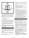
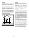
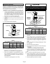
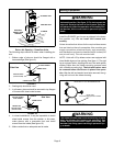
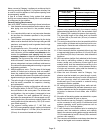
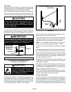
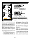
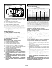
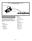
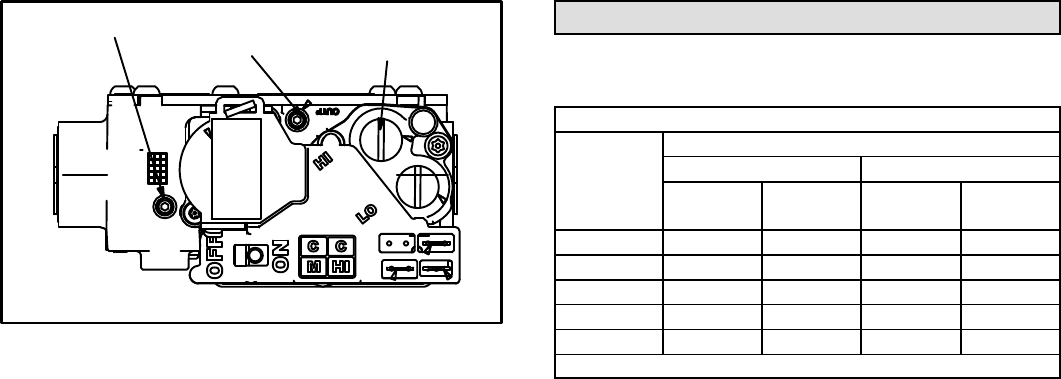
FIGURE 22
GAS VALVE SHOWN IN ON POSITION
INLET PRESSURE POST
HIGH FIRE ADJUSTMENT
SCREW
(under cap)
MANIFOLD
PRESSURE TAP
8 − Move switch on gas valve to ON. Do not force. See fig-
ure 22.
9 − Replace the upper access panel.
10− Turn on all electrical power to to the unit.
11− Set the thermostat to desired setting.
NOTE − When unit is initially started, steps 1 through 11
may need to be repeated to purge air from gas line.
12− If the appliance will not operate, follow the instructions
Turning Off Gas to Unit" and call your service techni-
cian or gas supplier.
Turning Off Gas to Unit
1 − Set the thermostat to the lowest setting.
2 − Turn off all electrical power to the unit if service is to be
performed.
3 − Remove the upper access panel.
4 − Move switch on gas valve to OFF. Do not force.
5 − Replace the upper access panel.
Failure To Operate
If the unit fails to operate, check the following:
1 − Is the thermostat calling for heat?
2 − Are access panels securely in place?
3 − Is the main disconnect switch closed?
4 − Is there a blown fuse or tripped circuit breaker?
5 − Is the filter dirty or plugged? Dirty or plugged filters will
cause the limit control to shut the unit off.
6 − Is gas turned on at the meter?
7 − Is the manual main shut-off valve open?
8 − Is the internal manual shut-off valve open?
9 − Is the unit ignition system in lock out? If the unit locks out
again, call the service technician to inspect the unit for
blockages.
10 − Is pressure switch closed? Obstructed flue will cause
unit to shut off at pressure switch. Check flue and outlet
for blockages.
11 − Are flame rollout switches tripped? If flame rollout
switches are tripped, call the service technician for in-
spection.
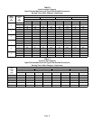
Gas Pressure Adjustment
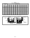
Gas Flow (Approximate)
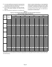
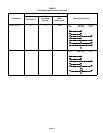
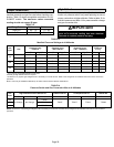
TABLE 11
GAS METER CLOCKING CHART
EL280DF
Unit
Seconds for One Revolution
Natural LP
1 cu ft
Dial
2 cu ft
Dial
1 cu ft
Dial
2 cu ft
DIAL
−045 80 160 200 400
−070 55 110 136 272
−090 41 82 102 204
−110 33 66 82 164
−135 27 54 68 136
Natural−1000 btu/cu ft LP−2500 btu/cu ft
Furnace should operate at least 5 minutes before check-
ing gas flow. Determine time in seconds for two revolu-
tions of gas through the meter. (Two revolutions assures a
more accurate time.) Divide by two and compare to time
in table 11. If manifold pressure matches table 13 and rate
is incorrect, check gas orifices for proper size and restric-
tion. Remove temporary gas meter if installed.
NOTE − To obtain accurate reading, shut off all other gas
appliances connected to meter.
Supply Pressure Measurement
An inlet post located on the gas valve provides access to
the supply pressure. See figure 22. Back out the 3/32 hex
screw one turn, connect a piece of 5/16 tubing and connect
to a manometer to measure supply pressure. See table 13
for supply line pressure.
Manifold Pressure
NOTE − Pressure test adapter kit (10L34) is available from
Lennox to facilitate manifold pressure measurement.
1 − Connect test gauge to manifold pressure tap (figure
22) gas valve.
2 − Ignite unit on high fire and let run for 5 minutes to allow
for steady state conditions.
3 − After allowing unit to stabilize for 5 minutes, record
manifold pressure and compare to value given in table
13.
4 − If necessary, make adjustments. Figure 22 shows
location of high fire adjustment screw.
5 − If an adjustment is made on high fire, re−check man-
ifold pressure on low fire. Do not adjust low fire man-
ifold pressure. If low fire manifold pressure is more
than 1/2" above or below value specified in table 13,
replace valve.
NOTE − Shut unit off and remove manometer as soon as an
accurate reading has been obtained. Take care to remove
barbed fitting and replace threaded plug.