KeypadLinc Schedule Timer Owner’s Manual
Page 9 of 26
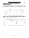
Step-by-Step Instructions for Installing Multi-Way KeypadLincs
When replacing a 3-way mechanical switch, each switch will have three wires connected to it from the wall box.
Four-way or greater circuits will have four wires connected to the switches in the center of the circuit. For this
tutorial, we will follow the most commonly used wire colors for homes in North America.
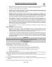
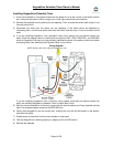
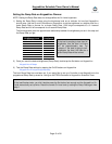
1) Find the LINE wire. Your first task is to find out which switch junction box is
the one where the electricity comes into the circuit. This box will contain the
LINE wire.
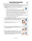
• Disable power at the circuit breaker or fuse panel
• Pull all the switches in the multi-way circuit out of their junction
boxes. Each switch should have three wires connected to it. If the
circuit is 4-way or greater, some of the switches will have four wires.
• Disconnect the wires from the old switches. If the wires cannot be detached by unscrewing them,
cut the wires where they enter the switch and then strip ½ inch of insulation off the ends.
• Making sure that none of the wires are touching anything and turn the electricity back on
• Using a volt meter or voltage tester, individually test each wire for voltage. When you measure
between 110 and 120 Volts AC, that wire is the LINE wire (usually black).
• The other two wires (usually black and red) are the TRAVELERS and go to the next junction box.
TRAVELER wires are usually in the same cable sheath.
• Turn off the electricity to resume installation
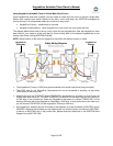
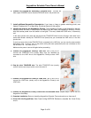
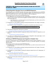
2) Connect the KeypadLinc Secondary’s LINE wire. The KeypadLinc that
will be the Secondary goes in the junction box where you found the LINE
wire. Connect the LINE wire that you found, the black TRAVELER, and the
KeypadLinc Secondary’s black LINE wire all together with a single wire nut.
3) Cap the other TRAVELER wire. The other TRAVELER wire (usually red)
will not be used, so put a wire nut on the end of it.
4) Cap the red LOAD wire from the KeypadLinc Secondary. Put a wire
nut on the end of the KeypadLinc Secondary’s LOAD wire to ensure that
it won’t connect to anything.
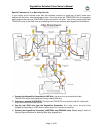
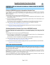
5) Connect the KeypadLinc Secondary’s NEUTRAL wire. Locate the
group of NEUTRAL wires (usually white) in the rear of the box. The old
switch should not have been connected to the NEUTRAL wires, but
KeypadLinc requires this con
nection in order to draw a small amount of
power for itself. Connect the KeypadLinc Secondary’s white NEUTRAL wire
to the other NEUTRAL wires with a wire nut.