VIDEO
VIDEO
S-VIDEO
VGA
VGA AUDIO
AUDIO
DVIAUDIO
AUDIO
COMPONENT IN
VIDEO IN
AV OUT
VGAIN
ANT IN
OPTICALOUT
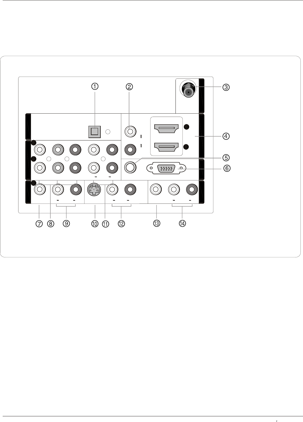
Back panel controls
Introduction
Owner s Manual 7
Connection Options
1. Digital Audio Output: Connect digital audio from various types of equipment.
NOTE: In standby mode, these ports will not work.
2. DVI Audio In: Connect a component video device to these jacks.
3. Antenna Input: Connect cable or antenna signals to the TV, either directly or through your cable box.
4. HDMI In: Connect a signal to HDMI.
5.VGA Audio In: Connect the audio L/R cables from a computer to this jack.
6.VGA Video In: Connect a video cable from a computer to this jack.
7. VIDEO In: Connects the video signal from a video device.
8. DVD/DTV In(Component ): Connect a component video device to these jacks.
9. AUDIO In: Connect the audio L/R cables from the video signal source to these jacks.
10. S-VIDEO In: Connect the S-Video cable from an external signal source to this jacks.
11. COMPONENT AUDIO In: Connect the audio L/R cables from the component video signal source to these jacks.
12. AUDIO In: Connect the audio L/R cables from the S-Video signal source to these jacks.
13. VIDEO Out: Connect the second TV or monitor to the TV`s AV OUT.
14. AUDIO Out: Connect the audio L/R cables to the second TV`s AV IN.


