YCS SW2 A • Installation and Operation
Installation and Operation, cont’d
2-14
YCS SW2 A • Installation and Operation
2-15
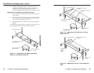
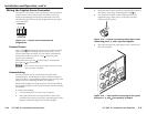
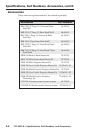
3. Insert the ends of the second wire into pin holes 2 and 3 of
the captive screw plug, connecting pins 2 and (3).
4. Use an Extron Tweeker or other small screwdriver to
tighten the plug’s three screws, so that the wire ends
remain securely in place.
1
2
V
ID
E
O
V
ID
E
O
A
U
D
IO
S
-
V
I
D
E
O
C
O
N
T
AC
T
A
U
T
O
-S
W
P
O
W
E
R
12V
0.4A
MA
X
IN
P
U
T
S
O
U
TP
U
T
1
1
IN
P
U
T
S
O
U
TP
U
T
2
2
L
R
R
L
R
E
MO
T
E
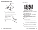
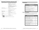
Figure 2-14 — Captive screw plug with jumper wires
connecting pins 1, 2, and 3 (ground) together
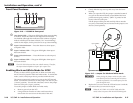
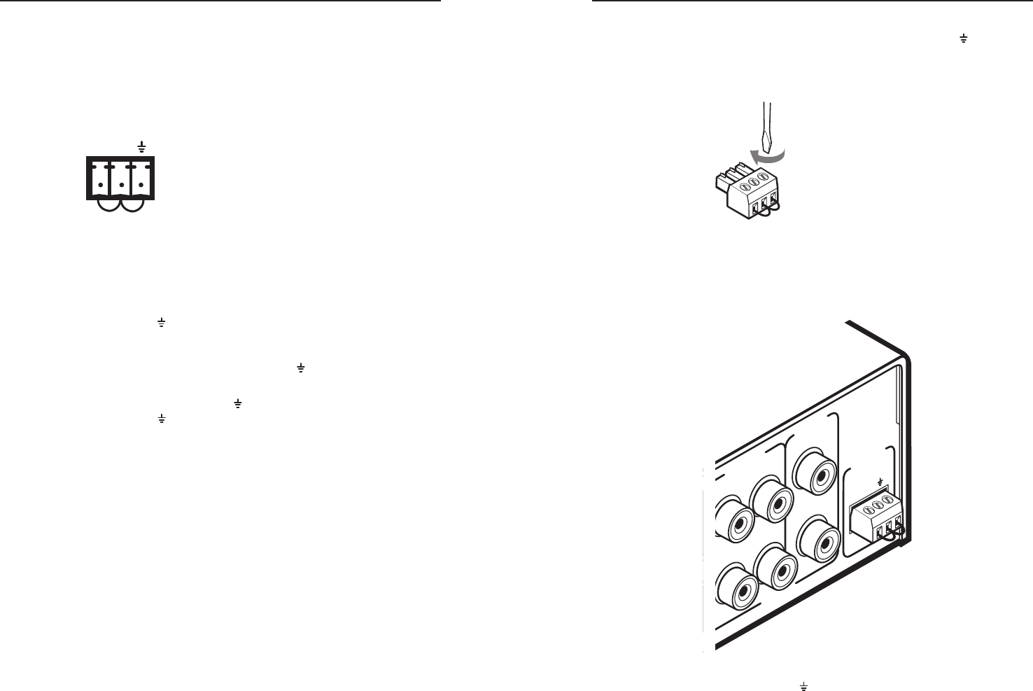
5. Insert the plug into the 3-pin captive screw connector on
the YCS rear panel.
1
2
VIDEO
VIDE
O
AU
DI
O
S-VIDEO
CONT
AC
T
AU
T
O-SW
PO
W
ER
12V
0.4A
MAX
INPUTS
OUTPUT
1
1
INPUTS
OUTPUT
2
2
L
R
R
L
RE
M
OT
E
Figure 2-15 — 3-pin captive screw plug in rear panel,
with pins 1, 2, and connected by a jumper
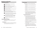
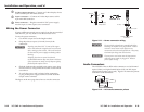
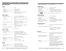
Wiring the Captive Screw Connector
The 3-pin, 3.5 mm captive screw connector is used for optional
remote contact closure control of the YCS SW2 A and/or to
enable autoswitching between inputs connected to the YCS.
The following figure shows the pin assignments for the captive
screw connector.
Pin #
Autoswitch
(Short to)
Contact Closure
Function
1
To Pin 3
Select Input #1.
Select Input #2.
2
3
To Pin 3
To Pin 2
To Pin 1
To Pin 2
1 2
CONTACT
AUTO-SW
To Pin 2
To Pin 1 and
Pin 3
Select Input #1.
Select Input #2.
Connect (Short to)
Figure 2-13 — Captive screw connector pin
assignments
Contact Closure
Pins 1, 2, and (ground) of the captive screw connector enable
input switching via a latching contact closure device. If you
want to select inputs remotely, you can connect a momentary
contact closure device to pins 1, 2, and of the rear panel
captive screw connector.
Momentarily short pin 1 to to select input 1; momentarily
short pin 2 to to select input 2.
N
If the contact closure inputs remain latched, front panel
input switching is disabled.
Autoswitching
You can set up the YCS to automatically select the active,
connected input. If both inputs are active, selection defaults to
input 2 (S-video). Autoswitching remains in effect as long as the
jumper wires are connecting the three pins together.
When autoswitching is in effect, the green Auto Switch LED on
the front panel lights, and the front panel input selection buttons
are disabled.
To enable autoswitching,
1. Cut two small pieces of wire to use as jumpers.
2. Insert the ends of one wire into pin holes 1 and 2 of the
provided 3-pin captive screw plug, connecting pins 1 and 2
together as shown in figure 2-14, on the next page.