XTRA Series • Operation
Operation
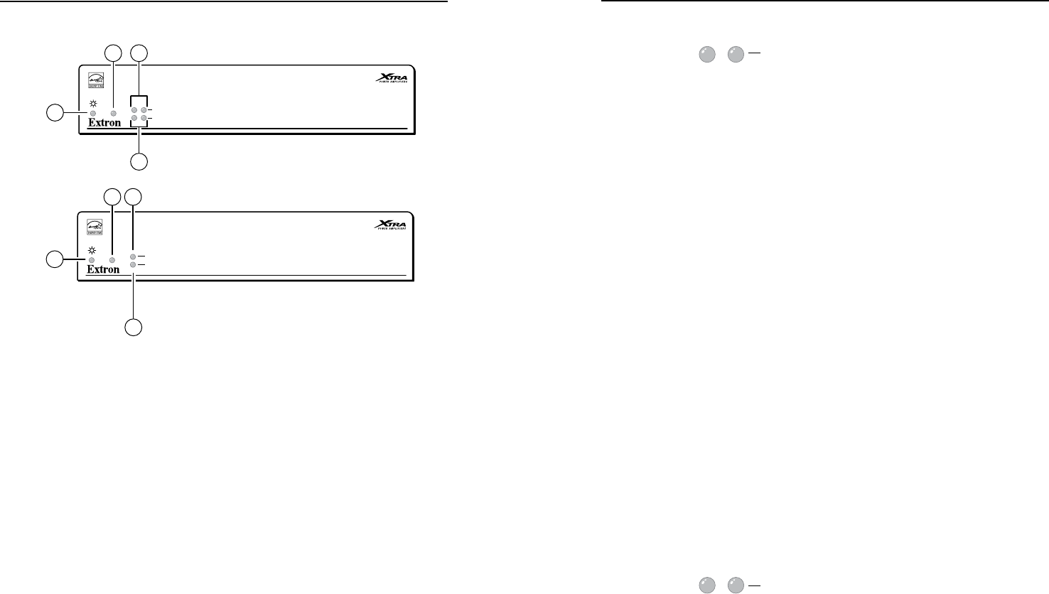
Front Panel Features and Operation
XPA 1002
12
LIMITER/PROTECT
SIGNAL
OVER
TEMP
XPA 1002
Front Panel
1
3a2
4a
XPA 2001
LIMITER/PROTECT
SIGNAL
OVER
TEMP
XPA 2001-70V,
XPA 2001-100V
Front Panel
3
b
2
4
b
1
a
Power indicator LED — This LED lights:
• Green when the amplier is receiving full power.
• Amber when the amplier is in Standby mode. Standby
mode turns off all outputs from the amplifier, although the
amplifier is still receiving power.
See
f
of “Rear Panel Features” in this chapter.
b
Over Temp indicator LED — This LED lights red when the
amplifier exceeds the recommended ambient temperature for
optimal lifetime. The LED will turn off after the amplier has
cooled down sufficiently.
Should the LED light, check the following:
• Verify that the placement of the amplier allows for adequate
ventilation and airflow.
• Avoid placing other equipment on top of the amplier.
• Verify that the operating temperature is within the specied
range.
Ñ
Limiter/Protect indicator LEDs (channels 1 and 2) — These
LEDs (representing output channels 1 and 2) light red under
four circumstances:
• When the output wiring is shorted together
• When audio clipping occurs, the corresponding channel’s
LED blinks once per clip occurrence.
• When the amplier overheats, both LEDs are lit. The LEDs
are not lit after the amplifier recovers from the overheated
condition.
• When DC output is detected, the amplier is malfunctioning
and the LED for the corresponding channel is lit. The
amplifier requires servicing when this event occurs.
N
These LEDs are also located on the rear panel.
Ö
Limiter/Protect indicator LED — This LED (representing the
output channel) lights red under four circumstances:
• When the output wiring is shorted together
• When audio clipping occurs, the LED blinks once per clip
occurrence.
• When the amplier overheats, the LED is lit. The LED is not
lit after the amplifier recovers from the overheated condition.
• When DC output is detected, the amplier is malfunctioning
and the LED is lit. The amplifier requires servicing when this
event occurs.
N
This LED is also located on the rear panel.
Ü
Signal indicator LEDs (channels 1 and 2) — These LEDs
(representing input channels 1 and 2) light green only when an
input signal is detected on the corresponding channel.
N
These LEDs are also located on the rear panel.
á
Signal indicator LED — This LED (representing the input
channel) lights green only when an input signal is detected.
N
This LED is also located on the rear panel.


