TLP 350MV • Setup Guide (Continued)
Mounting the TLP 350MV
Decide where to mount the TLP 350MV and whether to use a 3-gang mud ring or a 3-gang UL-certified junction box. The
mounting instructions are slightly different depending on your choice:
Using a Mud Ring
1. Use the template provided with the mud ring to mark
the wall. For the mud ring provided, the hole must be
5 25/32 inches (14.68 cm) wide x 3 7/8 inches (9.83 cm) high.
2. Cut a hole in the wall. To avoid making the hole too big, cut
inside the lines you marked.
3. Test the fit by inserting the mud ring into the hole in the wall.
If necessary, use a rasp or file to enlarge the hole.
4. Insert the mud ring into the hole and use a screw driver to
turn and tighten the locking arms until they clamp the mud
ring to the mounting surface. Do not overtighten.
5. Secure the wall adapter (provided) to the junction box, using
the four screws (provided).
6. Use the Extron removal tool provided to separate the bezel
from the TLP 350MV (see figure on previous page).
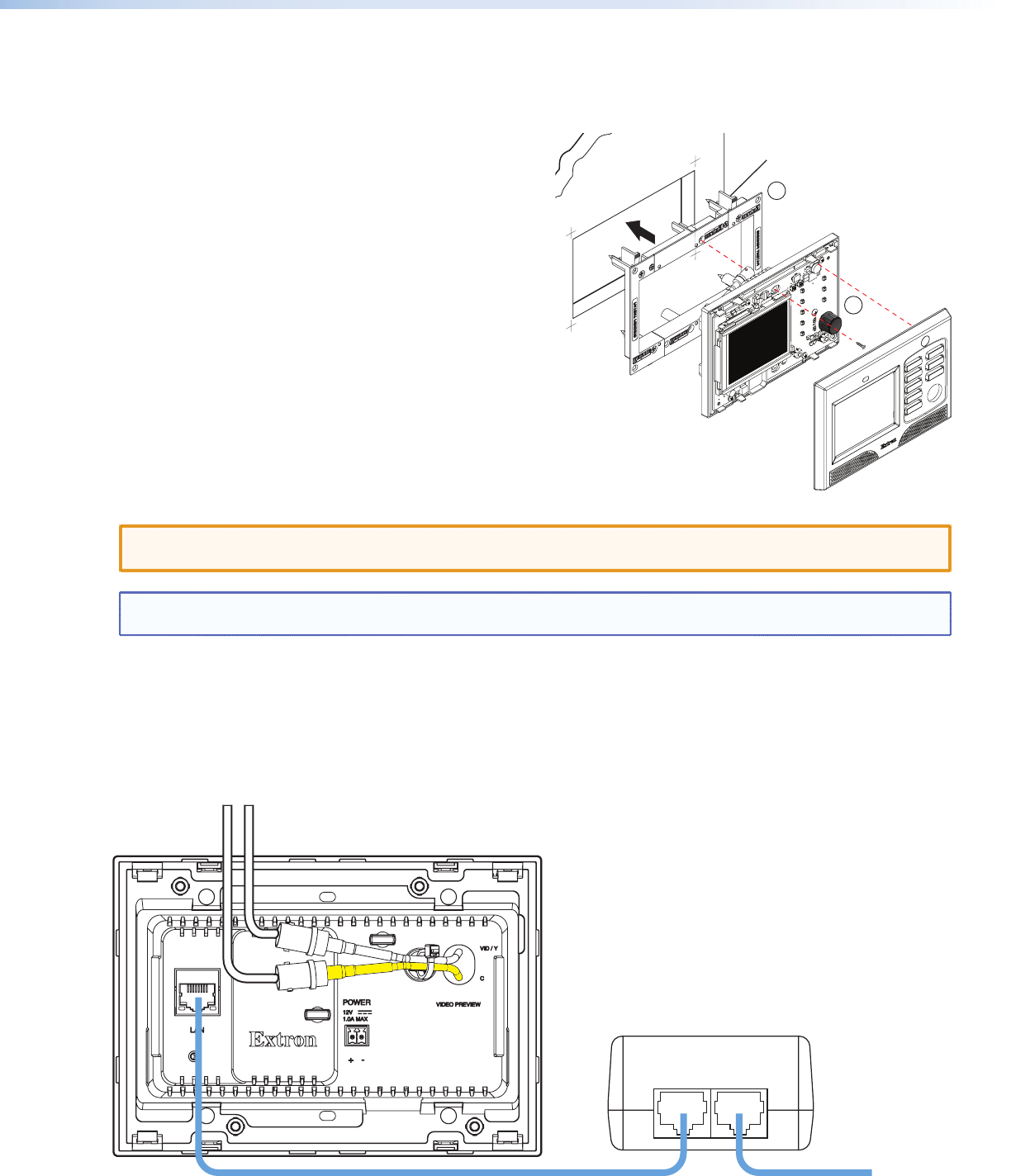
7. Extron recommends using the provided Power over Ethernet (PoE) power
supply. Connect a network switch to the "LAN In" port and run a second cable
from the "Pwr LAN Out" port to the Touch Panel mounting site (see the figure below).
CAUTION: Whether you use a PoE power supply or a 12 VDC power supply (not provided), you must read the
caution in the Power Supply section of the TLP 350MV User Guide.
NOTE: If both a PoE power supply and a 12 VDC power supply are present, the unit will draw power from the PoE
power supply only.
8. Run video cables with to the mounting site. Leave enough slack in the cables to connect them to the TLP 350MV. Pull
the cables through the mud ring. Connect the cables as shown in the diagram below.
9. Plug the cables into the rear panel connectors of the TLP 350MV (refer the TLP 350MV User Guide).
10. Secure the TLP 350MV to the mud ring using the two screws provided (top center and bottom center).
11. Do not replace the bezel at this time. You will need access to the recessed Menu and Reset buttons to configure the
unit.
PWR LAN-OUT LAN-IN
To Network SwitchTo TLP 350MV
Power over Ethernet (PoE) Power Supply
C (yellow cable) Video/Y (white cable)
Locking Arms (4)
Screws (2)
Clips (4)
Mud Ring
TLP 350MV
Bezel
PC
LAPTOP
DVD
DOC CAM
AUXILIARY
DISPLAY ON
DISPLAY OFF
MUTE
4
9


