3
3 — SOG (sync on green)
On — The interface outputs sync on green.
Off — The interface outputs separate horizontal and vertical sync (on the H and
V connectors) for RGBHV.
4 — V-Sync Width (vertical sync pulse width) — For some digital display devices, if no
picture appears, the picture cuts in and out, or the picture is scrambled, try adjusting the
output vertical sync pulse width or switching from ADSP to DDSP.
On — The vertical sync pulse is narrow.
Off — The vertical sync pulse is wide.
5 — Neg Sync — This switch controls sync polarity.
On — Both the horizontal and the vertical sync signals are forced to negative polarity on
output.
Off — Output sync polarity follows (is the same as) input polarity.
6 — Comp Sync — This switch controls composite sync output.
On — The interface outputs combined horizontal and vertical sync for RGBS.
Off — The interface outputs RGBHV or RGsB video.
Step 9 — RS-232 control
For two-way RS-232 communication, connect an RS-232 device (control system or PC) to the
3-pole captive screw connector. Software for RS-232 control is included with the interface.
Refer to the “Remote Control” section of chapter 3 of the user’s manual for further details.
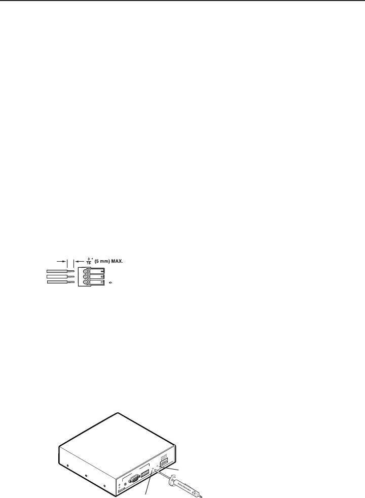
Wire the male connector, as shown here.
3-pin RS-232 Captive Screw Con_lateral.eps
Transmit
Receive
Ground
Tx
Rx
RS-232
Front Panel Adjustments
Video signals passing through long cable runs of over 125 feet (38.1 meters) can decrease
in strength, creating signal loss. The longer the cable, the greater the cable resistance and
capacitance, and the greater the level and peaking adjustments that will be required to
compensate for the resultant signal loss. These adjustments change the level and peaking of the
output signal to compensate for capacitance caused by up to 1000 feet (304.8 meters) of Extron
SHR cable.
N
If the displayed image is too bright or too dark, try changing the level setting. If the edges
of the displayed image seem to exceed their boundaries, or if thin lines and sharp edges look
thick and fuzzy, try changing the peaking setting. See the illustration below.
S
O
G
S
E
R
R
D
D
S
P
V-S
Y
N
C
W
ID
T
H
N
E
G
S
Y
N
C
C
O
M
P
S
Y
N
C
INPUTS
RGB 580xi
ANALOG
AUDIO
CONTROL
VIDEO
OUTPUT
LEVEL
A B C D E
PEAKING
Level
Peaking
1. Level adjustment control — The Video Output Level control alters the bright ness of the
displayed image. To adjust the video output level, view the display while using a small,
flat-blade screwdriver to rotate this potentiometer.
If the interface receives a typical (0.7 volts p-p) analog computer video input, the output is
as follows:


