Installation
1 PA 250 • Introduction PA 250 • Installation
Introduction
3
Installation, cont’d
2PA 250 • Installation
The Extron PA 250 is a long-line peaking amplifier for driving RGB
video up to 1,000 feet. It can also be used as a sync stabilizer to
eliminate jitter. Other features include:
• RGB video bandwidth of 250 MHz
• Sync combining, boost, and sharpness capabilities
• Automatically strips incoming sync from the red, green, and blue
channels.
The quality of the image depends on the quality of all of the
components in your video system, including the cables.
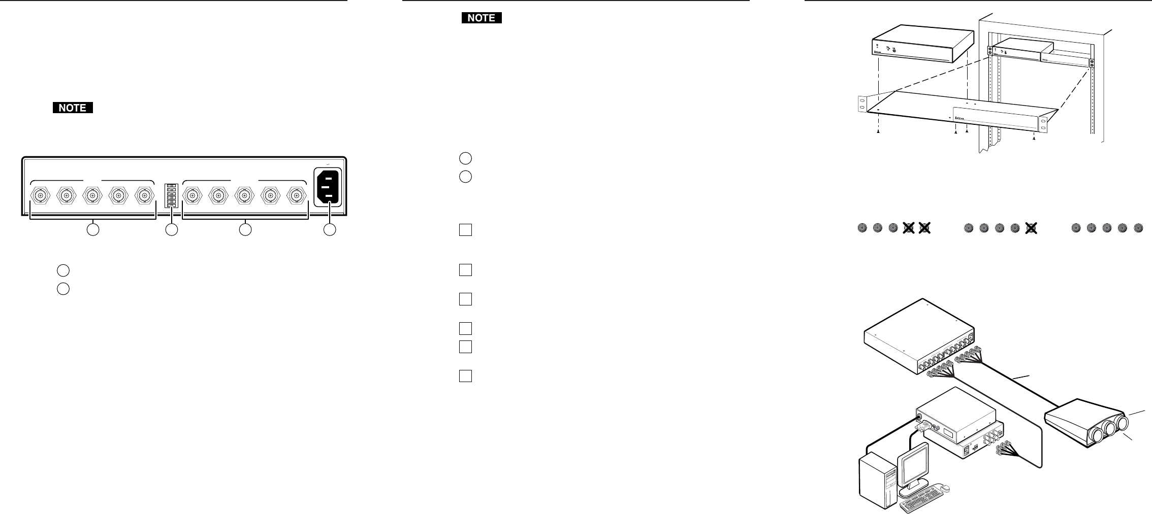
Rear Panel Connectors and Controls
R G B H/HV V R G B H/HV V
50/60 Hz
100-240V 0.2A MAX
INPUT OUTPUT
123456
1
2
3
4
5
6
2 41 3
Figure 1 — PA 250 rear panel
1
Input BNC connectors — Attach to the input device.
2
DIP switches — The default for all switches is Off. If switches 1,
2, and 6 are Off, sync output depends on the impedance of the
output cables (75 ohm on RGB cables, up to 1 kohm on sync lines).
1 — SOG defeat
On — Sync on green (SOG) is not allowed. This setting
prevents the PA 250 from outputting an RGsB signal.
Off — Automatic sync detection is used (default setting).
2 — Force H&V
On — H and V sync are always separated. This setting
prevents the PA 250 from outputting an RGBS signal.
Off — Automatic sync detection is used (default setting).
3 — Force negative sync
On — Sync pulses are always negative.
Off — Sync output polarity follows input polarity.
4 — Serration pulse removal
On — Serration pulse are removed from the output vertical
sync pulse. LCDs, DLPs and plasma displays must
have the serration pulses removed to display properly.
Flagging or bending at the top of the video image is a sign that
the serration pulses should be removed.
Off — Serration pulses pass through the PA 250.
5 — Pulse width
On — Vertical sync pulse width = 500 µseconds.
Off — Vertical sync pulse width = 150 µseconds.
6 — Digital display sync processing™ (DDSP™)
On — LCD (digital display) sync processing is on.
Off — Normal sync processing is active.
3
Output BNC connectors — Attach to the output device.
4
AC power input connector — Attach a standard IEC power cord
(100VAC to 240VAC, 50/60 Hz).
Installation Overview
1
Turn all of the equipment off. Ensure that the source device, the
PA 250, and the output device are turned off and disconnected
from the power source.
2
If desired, mount the PA 250 in a rack. See “Mounting the
PA 250” below.
3
Cable the inputs and outputs to the PA 250. See “Cabling” on
page 3.
4
Set the rear panel DIP switches. See (2) on page 1.
5
Plug the input device, the PA 250, and the output device into a
grounded AC source.
6
Turn on the input and output devices.
Mounting the PA 250
If desired, mount the PA 250 to a rack shelf (Extron part number
60-190-01) as follows:
1. If feet were installed on the bottom of the PA 250, remove them.
2. Mount the PA 250 on the rack shelf, using two 4-40 x 1/8 screws
in opposite (diagonal) corners to secure the case to the shelf.
3. Attach the false front panel (provided with the rack shelf) to the
unoccupied side of the rack, or install a second half-rack device.
4. Attach the rack shelf to the rack using four 10-32 x 3/4” bolts
(provided). Insert the bolts through the #10 beveled washers,
then through the holes in the rack ears and rack.
4-40 X 1/8 Screws
Use 2 Mounting Holes
on Opposite Corners
False Front Panel
Uses 2 Front Holes Only
PA 250
PEAKING AMPLIFIER
PA
250
P
E
A
K
I
N
G
A
M
P
L
I
F
I
E
R
Figure 2 — Rack mounting the PA 250
Cabling
Connect input and output cables to the PA 250 as shown below.
RGsB (sync on green)
R
H/HV
G B
V
R
H/HV
G B
V
R
H/HV
G B
V
RGBS
RGBHV
The PA 250 can be attached to an input device, such as an interface
connected to a personal computer, and to an output device, such as a
large screen projector. The following figure shows a typical application.
Projector
PC Computer
Interface
RGB 109xi
Up to 1000'
O
U
T
P
U
T
SOG OUT
DDSP
SERR
SPARE
Rear
5
0
/
6
0
H
z
1
0
0
-
2
4
0
V
0
.
5
A
L
E
V
E
L
/
P
E
A
K
0
.
8
V
5
0
%
U
N
I
T
Y
0
.
9
V
1
0
0
%
B
U
F
F
E
R
E
D
L
O
C
A
L
M
O
N
I
T
O
R
O
U
T
P
U
T
I
N
P
U
T
H
.
S
H
I
F
T
R
G
B
1
0
9
x
i
V
G
A
I
N
T
E
R
F
A
C
E
W
/
A
D
S
P
Front
I
D
P
I
N
4
I
D
P
I
N
1
1
PA 250
0
.
3
5
A
1
0
0
-
2
4
0
V
5
0
-
6
0
H
z
OU
TPU
T
G
H
/
H
V
V
B
R
G
H
/
H
V
V
B
R
IN
PU
T
Figure 3 — Typical PA 250 application


