Installing Enclosure Components 65
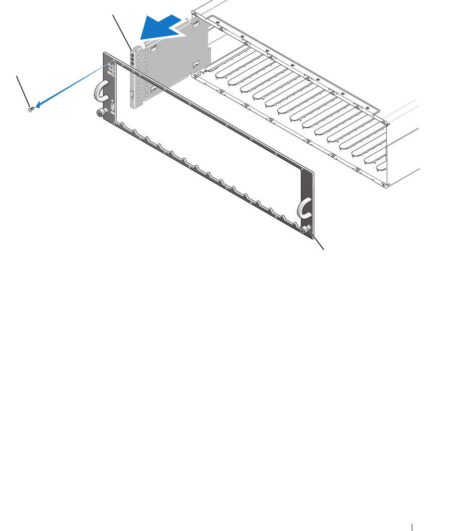
Figure 4-7. Removing and Replacing the Control Panel
6
Using a Torx T10 driver, remove all 16 screws from the front faceplate of the enclosure as shown in
Figure 4-7.
7
Remove the front faceplate from the enclosure and place it on a flat, secure surface.
8
Slide the control panel assembly straight out from its connector on the backplane (see Figure 4-7).
Installing the Control Panel
1
Align the top and bottom tabs on the control panel with the insert slots on the edge of the chassis (see
Figure 4-7).
2
Slide the control panel fully into the slot, making sure that its connector engages into the matching
backplane connector (see Figure 4-7). Also, make sure the guide tab on the control panel is fully
inserted into the mounting slot on the backplane.
3
Replace the front faceplate and re-attach the 16 screws that hold it in place.
4
Re-install any
physical disk
s you removed (see "Removing and Installing Physical Disks" on page 56).
5
Push the enclosure all the way back into the rack and tighten the thumbscrews.
1 faceplate screws (16) 2 control panel 3 thumbscrews
3
1
2


