4
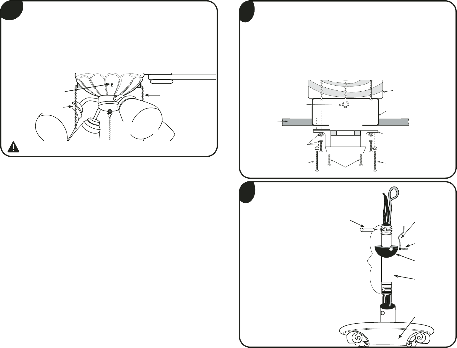
OUTLET BOX
Outlet Box (A)
Mounting Bracket (1)
Bracket Screws
& Washers (S3)
Support Beam
Wood Screws (S1)
Canopy Screws (S2)
Ceiling
Wood Screws (S1)
“J” Hook (S10)
Fan Motor Housing
Hanging Ball
Lock Pin
Downrod
Ball Screw
Green Ground
Wire
Downrod
Assembly
(#2)
5
Step 5
Locate downrod
assembly (#2). Loosen
ball screw on black
hanging ball to free lock
pin. Black hanging ball
will slide down. Remove
ground screw and green
ground wire. Remove
hanging ball from
downrod and save all
parts. Insert fan wires
through downrod. Screw
downrod into top of fan
motor housing, being
careful that wires are
pulled through.
14
Interrupteur à
glissière
Chaîne de traction
du moteur
Chaîne de traction
de l’éclairage
ATTENTION: même si les pales de votre ventilateur sont installées à plus 2 mètres du
sol, évitez toujours de placer vos bras ou tout objet sur leur chemin de rotation.
Chaîne de
force de Uplight
Mode d'emploi
1. La séquence de fonctionnement de la chaîne de traction/interrupteur du moteur est
OFF-HI-MED-LOW.
2. Faites glisser l'interrupteur vers la DROITE pour faire tourner le ventilateur EN
AVANT ou faites-le glisser vers la GAUCHE pour faire tourner les pales dans l'autre
sens.
3. La chaîne de traction/interrupteur de l’éclairage a deux positions : ON/OFF
[MARCHE/ARRÊT].
4. La chaîne de traction/interrupteur de l’éclairage vers le haut a deux positions :
ON/OFF. REMARQUE : l’éclairage vers le haut nécessite 3 ampoules candélabres
de 60 W. (Non fournies).
Step 4
Prior to securing mounting bracket, screw "J" hook (S10) into ceiling
outlet box as a secondary support means. Secure mounting bracket (1) to
the outlet box (A) by tightening bracket screws & washers (S3) as shown.
If not mounting to an outlet box, use wood screws (S1) and washers (S3)
and mount securely to ceiling beam. Be sure at this point to insert canopy
screws (S2) in bracket. NOTE: Do not mount directly to sheet rock or ceiling tile.
NOTE: J Hook installation is a Canadian requirement only.


