Compur Statox 4120
Example of cable specifications:
Max. cable capacity: l x C
L
= C
o
- C
i
= 107 nF
Max. cable inductivity: l x L
L
= L
o
- L
i
= 6,6 mH
Diameter: > 0,75 mm
2
The Statox 4120 Systems will work reliably if the electrical resistance is : R
L
< 50 Ω.
Most commonly the maximum length is limited by the cable capacity.
Example: Cable diameter is 1,0 mm
2
(0,04 in), C
L
= 90 pF/m, L
L
= 0.7mH/km, R
L
/ km = 19,5 Ω.
The maximum cable length results to be
l =
mpF
CiCo
/90
−
= 1189 m (3900 ft), the electrical resistance is
R
L
= 2 x 1.189km (0,738 miles) x 19,5 Ω/km = 46,4Ω. So R
L
< 50Ω is OK.
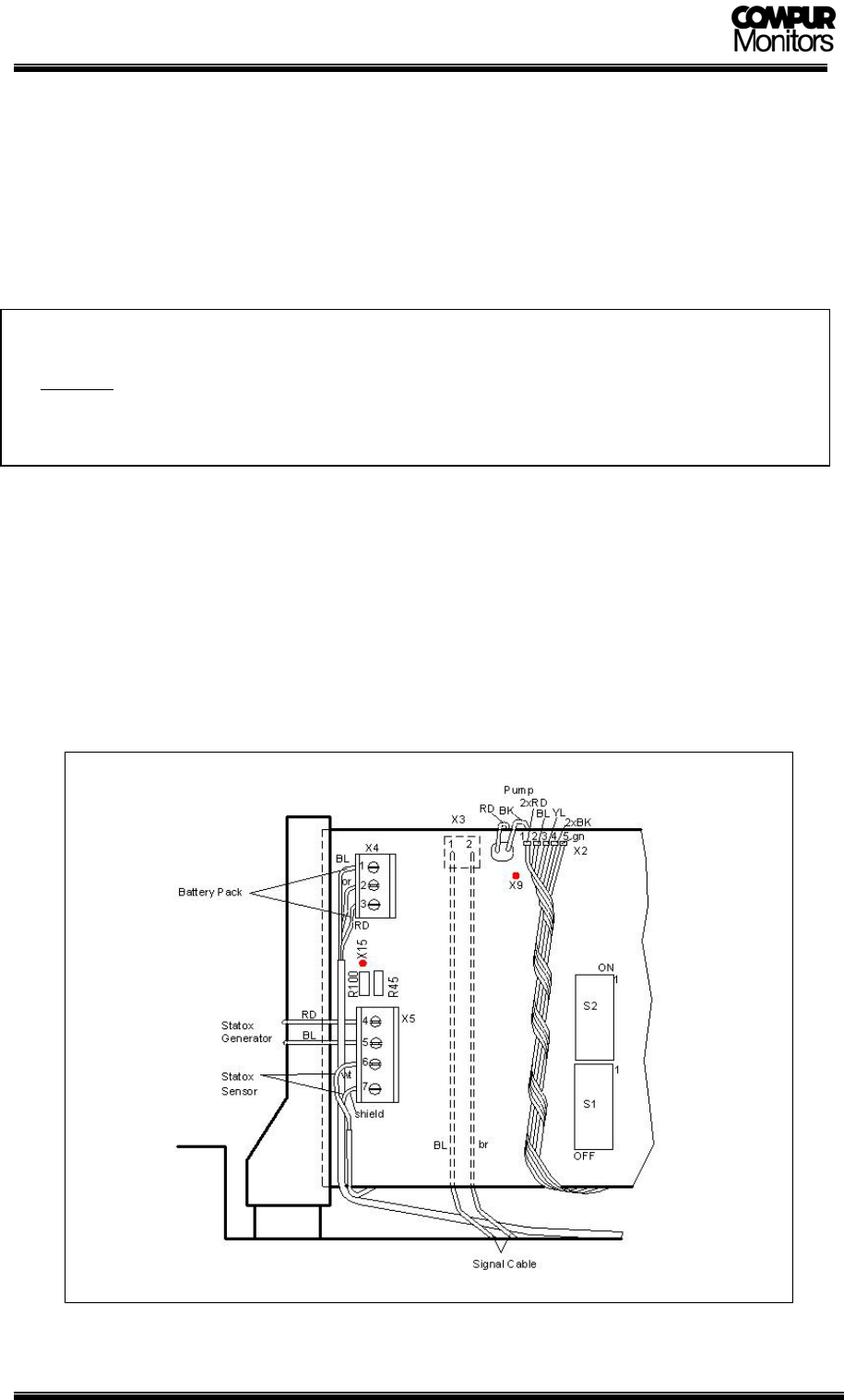
Sensor head connection procedure:
Open sensor head, remove cable gland.
Connect signal cable to terminals X3/1 und X3/2, polarity does not matter.
(DIN EN 60079-14 chapter 12 is applicable)
Fasten cable gland.
Connect battery pack: - Blue to terminal X4/1
- Orange to terminal X4/2
- Red to terminal X4/3
Connect signal cable to backplane of the rack. (See chapter 3.2)
pic.9: Sensor head pcb terminals
12


