2-32
Cisco CRS Carrier Routing System 8-Slot Line Card Chassis Installation Guide
OL-6256-17
Chapter 2 Installing and Removing Power Components
How to Install or Remove Modular Configuration Power Components
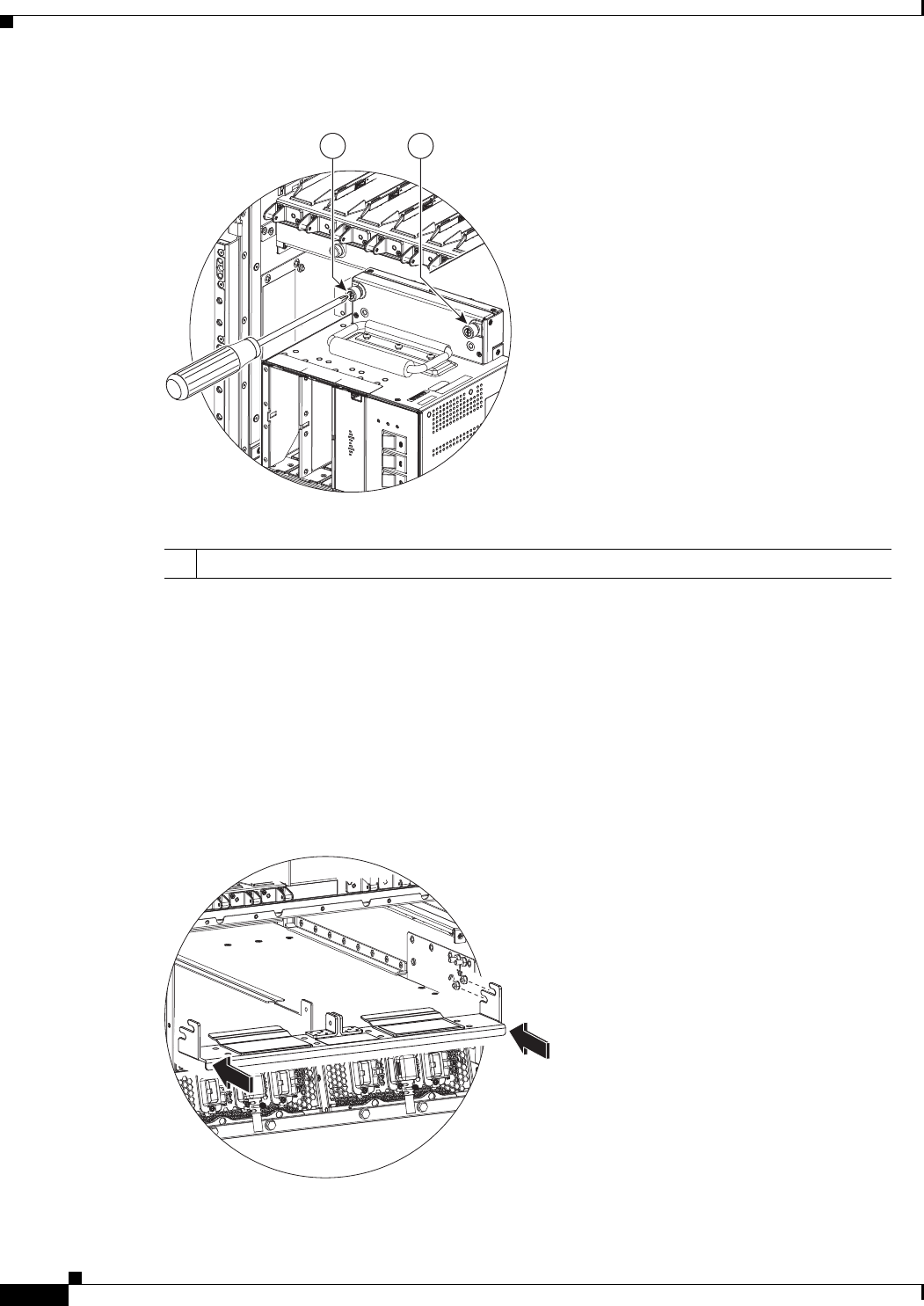
Figure 2-21 Fastening the Power Shelf to the Chassis
Step 8
Remove the ESD-preventive wrist strap from the front (PLIM) side of the chassis. Go to the rear of the
chassis and reattach to one of the ESD connection sockets on the rear (MSC) side of the chassis or a bare
metal surface on the chassis.
Step 9 Using the 10-mm wrench, install the hex head bolts to secure the power shelf to the cross bracket, as
shown in Figure 2-25.
Step 10 Insert the modular configuration power shelf cross bracket on the mounting studs, two on each side of
the chassis, as shown in Figure 2-22. Then install the four M6 nuts, two on each chassis side, and tighten
with the 10-mm combination wrench as shown in Figure 2-23.
Figure 2-22 Installing Modular Configuration Power Shelf Cross Bracket
1 Screws to tighten and secure power shelf to chassis.


